Vibrating screen

A technology of vibrating screens and vibrating rods, which is applied in the direction of filter screens, mobile filter element filters, grilles, etc., which can solve the problems of large foundation vibration force, large screen box structure, screen vibration, etc., and achieve small vibration quality, There are many adjustable parameters and the effect of uniform vibration

Inactive Publication Date: 2011-01-05
李卓
View PDF5 Cites 6 Cited by
  • Summary
  • Abstract
  • Description
  • Claims
  • Application Information

AI Technical Summary

Problems solved by technology

When the integral vibrating vibrating screen is working, the screen box and the screen surface vibrate together. The screen box has a huge structure, high energy consumption, and a large vibration force on the foundation. In addition, due to the high rigidity of the screen box, it also hinders the enlargement of the vibrating screen; When the screen vibrating vibrating screen is working, the screen is fixed on the screen box, usually by tapping or pulling the screen to vibrate part of the screen, resulting in low utilization of the screen and uneven vibration, and rapid wear of the screen

Method used


Image

  • Vibrating screen
  • Vibrating screen
  • Vibrating screen

Examples


Embodiment 1

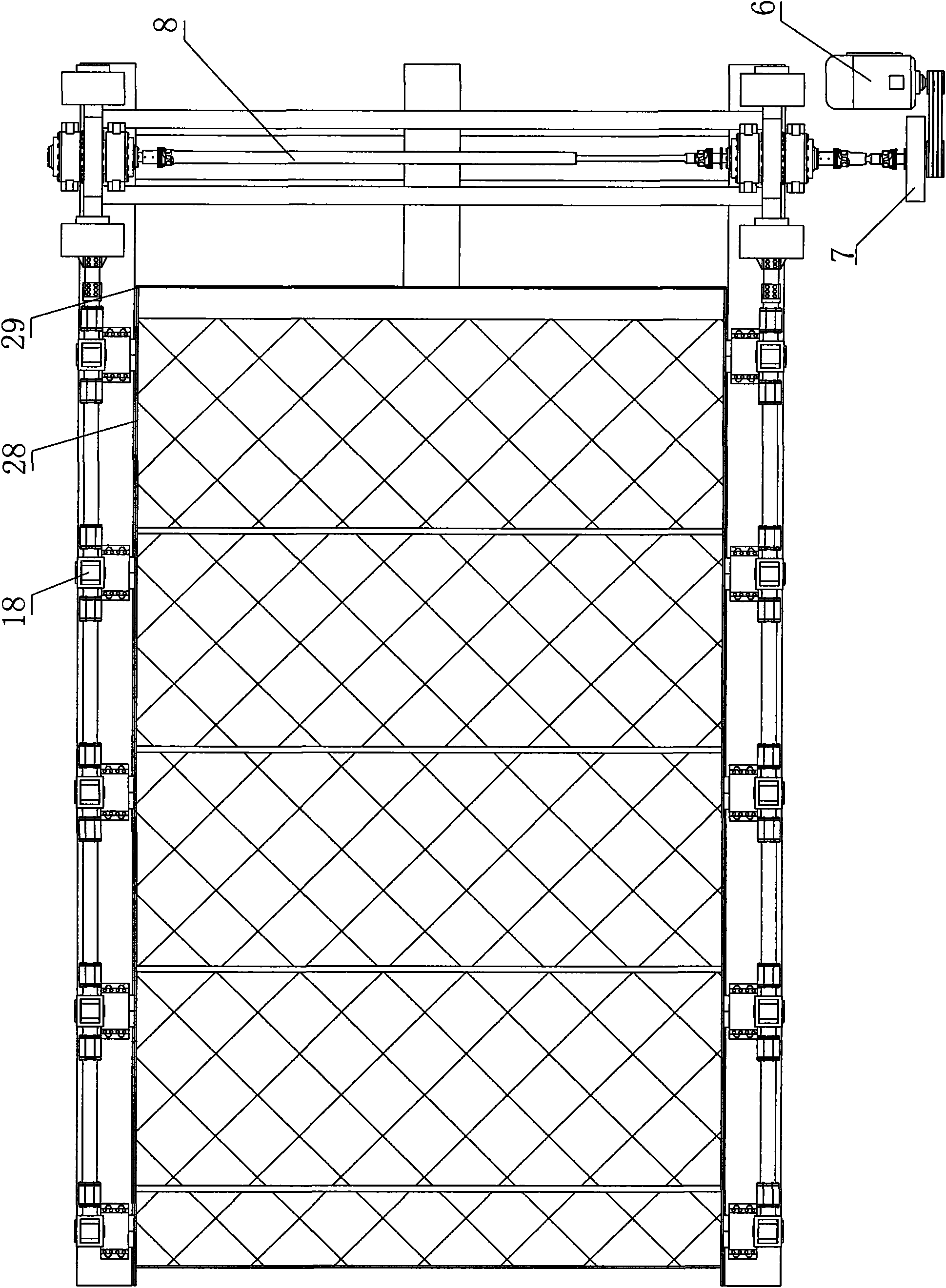
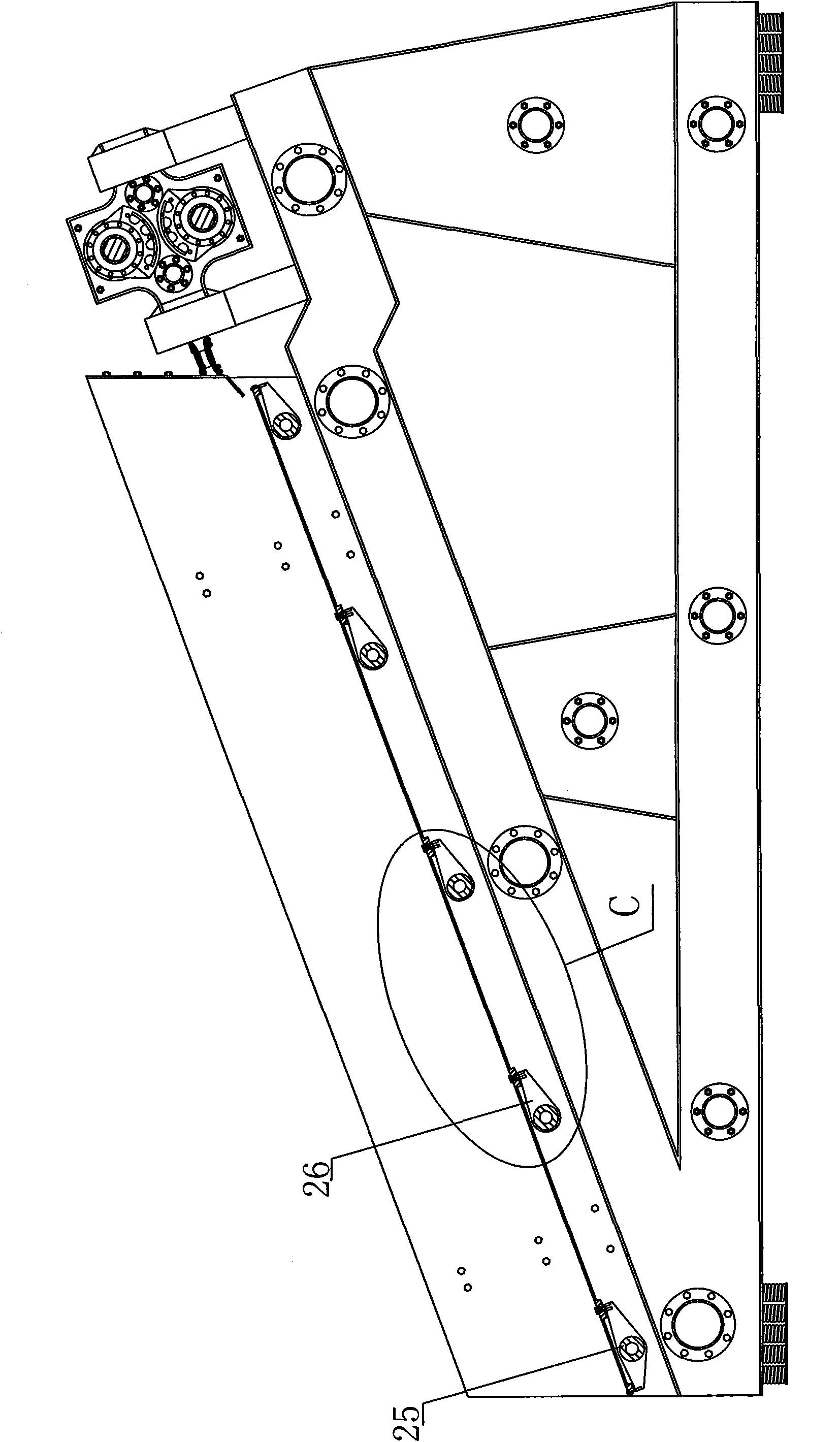
[0024] Example 1, such as Figure 1 to Figure 4 As shown, the vibration excitation device 1 is fixed on the tail of the frame 9, the vibration exciter 2 is installed on the vibration exciter seat 3, the vibration exciter seat 3 is installed in the exciter frame 5 through the spring 4, and the vibration screen on both sides The vibration excitation device 1 is connected by a universal coupling 8, a synchronizer 7 is set between the vibration excitation device 1 and the motor 6, the transmission mechanism 10 is connected with the vibration excitation device 1 through an elastic plate 11, and the transmission rod 12 is a multi-stage type , through the adjustment sleeve 13 and the connection sleeve 14 connected together, the upper end of the vibrating rod 17 is provided with an elastic connector 18, the lower end of the vibrating rod 17 is set on the end of the rotating shaft 25, each rotating shaft 25 is hinged by three elastic The support base 22 is installed on the frame 9, the...

Embodiment 2

[0031] Example 2, such as Figure 10 to Figure 13 As shown, the vibrating device 31 is fixed on the frame 36, the vibrator 33 is a forced synchronous vibrator, the vibrator 33 is installed in the vibrator frame 32 through a spring 34, and the motor 35 drives the vibrator 33 through a pulley , the transmission mechanism 37 is connected with the vibration excitation device 31, the transmission rod 38 is a two-stage type, an adjustment sleeve 39 and a connecting sleeve 40 are respectively installed on both sides of the vibration excitation device 31, and the upper end of the vibration rod 41 is provided with an elastic connector. The lower end of the vibrating rod 41 is sleeved on the end of the rotating shaft 43, each rotating shaft 43 is installed on the frame 36 through two bearing seats 42, the vibrating arms 44 are arranged on the rotating shaft 43, and the spring steel wire mesh 45 passes through the bolt Fastened on the vibrating arm 44, the frame 36 is provided with a sid...


PUM


Abstract

The invention discloses a vibrating screen with a vibrating screen surface and static screen box and aims to provide a vibrating screen which is low in energy consumption and foundation vibrating force and can be made in large size easily. The vibrating screen comprises a machine frame, a screen surface, a vibrating device and a transmission mechanism, wherein the transmission mechanism comprises a transmission rod, vibrating rods, rotating shafts, rotating shaft seats and a vibrating arm, wherein the vibrating device is connected with the transmission rods; the transmission rod is hinged with the vibrating rod, the vibrating rod is sleeved on the ends of the rotating shafts; the rotating shafts are arranged in the rotating shaft seats; at least two rotating shaft seats are arranged on each rotating shaft; the vibrating arms are arranged on the rotating shafts; the rotating shaft seats and the vibrating device are arranged on the machine frame; and the screen surface is fastened on the vibrating arms by bolts. The vibrating screen can be widely used in energy resource, metallurgical, ceramic, building material, chemical industries and other industries and mainly used for material grading and dehydration.

Description

technical field [0001] The invention relates to a vibrating separation device, in particular to a vibrating screen whose screen surface vibrates but the screen box does not vibrate. Background technique [0002] At present, vibrating screens are widely used in energy, metallurgy, ceramics, building materials, chemical industries and other industries. They are mainly used for material classification and dehydration. Vibrating screens mainly have two forms: integral vibration type and screen vibration type. When the integral vibrating vibrating screen is working, the screen box and the screen surface vibrate together. The screen box has a huge structure, high energy consumption, and a large vibration force on the foundation. In addition, due to the high rigidity of the screen box, it also hinders the enlargement of the vibrating screen; When the screen vibrating vibrating screen is working, the screen is fixed on the screen box. Generally, part of the screen is vibrated by tap...

Claims


Application Information

Patent Timeline
Patent Type & Authority Applications(China)
IPC IPC(8): B07B1/28B07B1/42B07B1/46B01D33/00
Inventor 李卓
Owner 李卓
Why Eureka
Try Eureka