Magnetic circuit structure of high-central-field magnetic shoe mould

A high-center, center-field technology, applied in the field of magnetic circuit structure of molds, can solve problems such as large influence relationship of orientation, unsatisfactory motor operation characteristics such as torque and noise, unsatisfactory surface magnetic field strength and center field, etc. To achieve the effect of improving mechanical properties

Active Publication Date: 2011-01-05
安徽金寨将军磁业有限公司
View PDF3 Cites 7 Cited by
  • Summary
  • Abstract
  • Description
  • Claims
  • Application Information

AI Technical Summary

Problems solved by technology

As mentioned above, the performance of the final magnetic properties of the magnetic tile is closely related to the orientation of the forming magnetic field it receives during forming. The products produced by the mold designed in the traditional way are ultimately limited by the degree of magnetic concentration of the magnetic circuit. , so that the surface magnetic field

Method used


Image

  • Magnetic circuit structure of high-central-field magnetic shoe mould
  • Magnetic circuit structure of high-central-field magnetic shoe mould
  • Magnetic circuit structure of high-central-field magnetic shoe mould

Examples


Embodiment 1

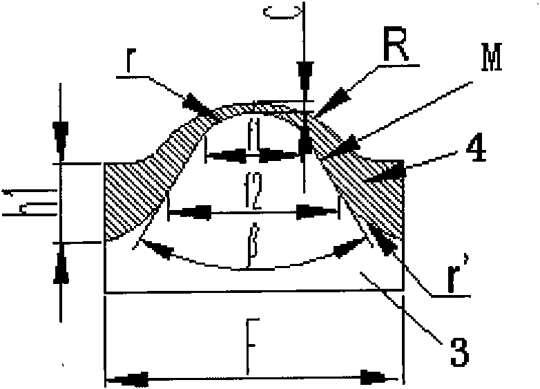
[0047] The product specification selected in this embodiment is a permanent magnet ferrite tile-type magnet for a micro-motor. The internal code of the product is W-284. For the specification and shape, see Figure 5 , where T is the placement point of the Hall probe when measuring the surface magnetic field strength.

[0048] Forming uses a slurry with a grinding particle size of 0.85. The main properties of the material: the residual magnetism is greater than 3950 Gauss, and the intrinsic coercive force is greater than 3850 Oersted.

[0049] The measurement and comparison results of the final product are shown in Table 1

[0050] Measurement items: inner arc median surface magnetic field strength and center field strength.

[0051] Apparatus used: WT-3A digital millitesla meter produced by Nanjing University Hengtong Technology Development Company.

[0052] Table 1

[0053]

[0054] It can be seen from the comparative data in Table 1 that the effect of the new magneti...

Embodiment 2

[0056] This example uses the same material as the previous example, and the product specification is R16.9*r12*W30*L37.


PUM

PropertyMeasurementUnit
Thicknessaaaaaaaaaa
Intrinsic coercive forceaaaaaaaaaa

Abstract

The invention relates to a magnetic circuit structure of a high-central-field magnetic shoe mould, which comprises an upper punch head and a lower punch head, wherein the upper punch head and the lower punch head are made of magnetic-conducting materials, a magnetic-conducting material layer is respectively embedded between the molding surfaces of the upper punch head and the lower punch head and a basal body to form a magnetic-flux refracting surface, and the shape of the magnetic non-conducting material embedded layer of the upper punch head is formed from a line segment L and a line segment L1 at both sides and a line segment B at the top end, wherein the line segment L and the line segment L1are straight line segments, the line segment B is an arc line segment or a straight line segment, an included angle alpha is 50-72 degrees, the embedded shape of the lower punch head is formed from an arc line at the top end, straight lines at both sides and an arc line at the bottom side, and an included angle beta=2(90 degrees-alpha)+0-11). In the invention, the upper punch head and the lower punch head, made of the magnetic-conducting materials, are respectively embedded into the magnetic non-conducting material layer with the finely designed shape to form the more effective magnetic-flux refracting surface, thereby realizing that magnetic particles are subjected to the action of a more ideal polymerization magnetic field to carry out more appropriate orientation when a blank body is molded, realizing the high central field and the high middle-position surface magnet of a magnetic shoe and generating an active contribution to effectively improving the mechanical characteristic of a motor.

Description

technical field [0001] The invention relates to a magnetic circuit structure of a mold used for wet and dry forming of permanent ferrite magnets, in particular to a magnetic circuit structure capable of significantly increasing the central magnetic field intensity of a tile-shaped magnet. Background technique [0002] "Forming" in the process flow of permanent ferrite wet and dry production of tile-shaped magnets is the basic process that determines the shape and magnetic performance characteristics of the final product. The magnetic field intensity and distribution characteristics provided by the magnet to the air gap during use will have a greater impact on the operating characteristics of the micromotor. [0003] In the process of long-term cooperation with customers, we found from the information feedback from customers, such as Figure 6 The products installed in the motor casing 5 produced by the mold of the traditional magnetic circuit structure as shown usually show ...

Claims


Application Information

Patent Timeline
IPC IPC(8): B28B7/00
Inventor 万遥
Owner 安徽金寨将军磁业有限公司
Why Eureka
Try Eureka