Cooling chamber assembly for a gasifier

A technology for cooling chambers and gasifiers, which is applied in the field of gasifiers and can solve problems such as operational problems

Inactive Publication Date: 2011-01-05
GENERAL ELECTRIC CO
View PDF1 Cites 9 Cited by
  • Summary
  • Abstract
  • Description
  • Claims
  • Application Information

AI Technical Summary

Problems solved by technology

However, it was found that excess liquid carried away from the cooling chamber and into downstream equipment caused operational problems

Method used


Image

  • Cooling chamber assembly for a gasifier
  • Cooling chamber assembly for a gasifier
  • Cooling chamber assembly for a gasifier

Examples


Embodiment Construction

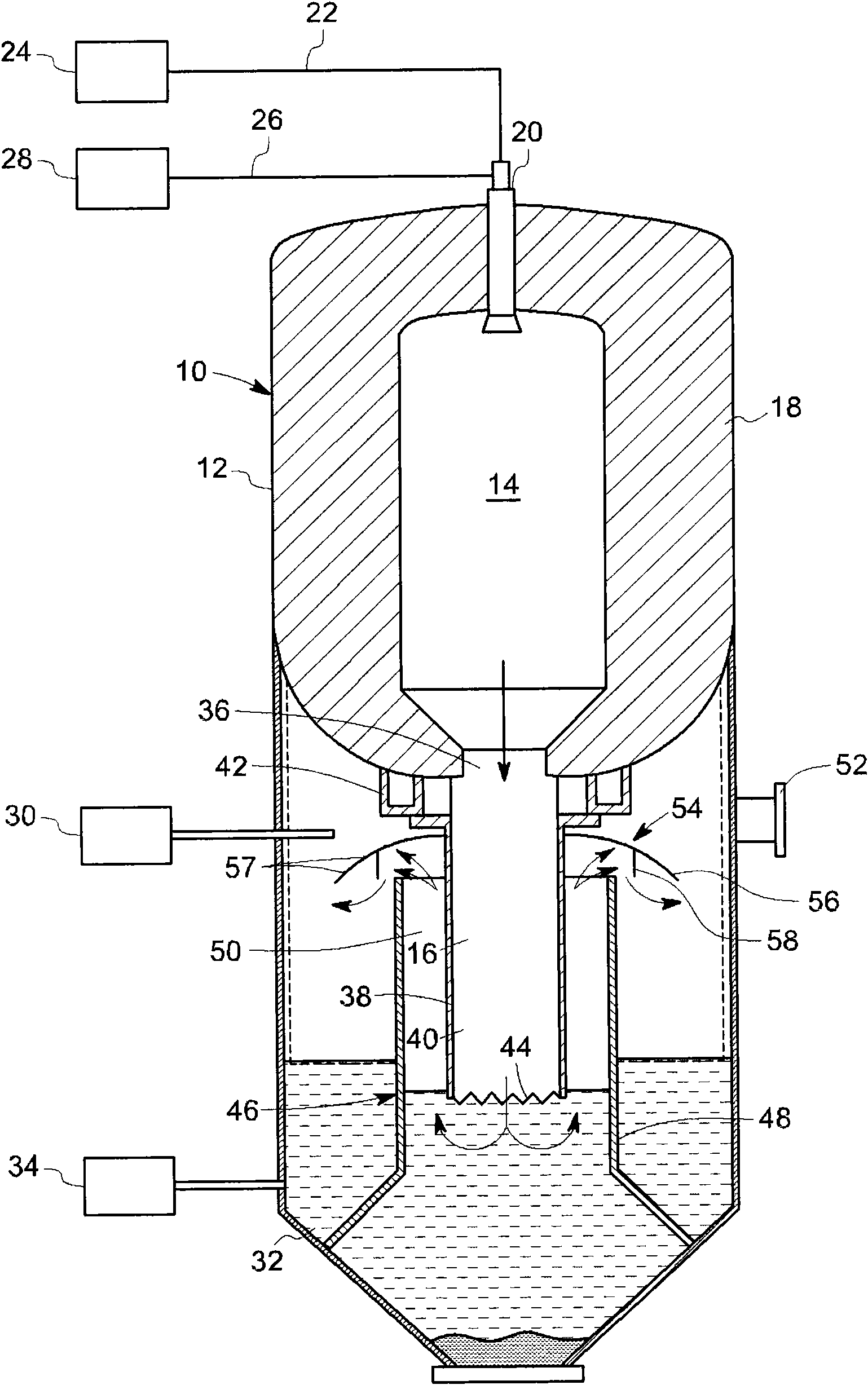
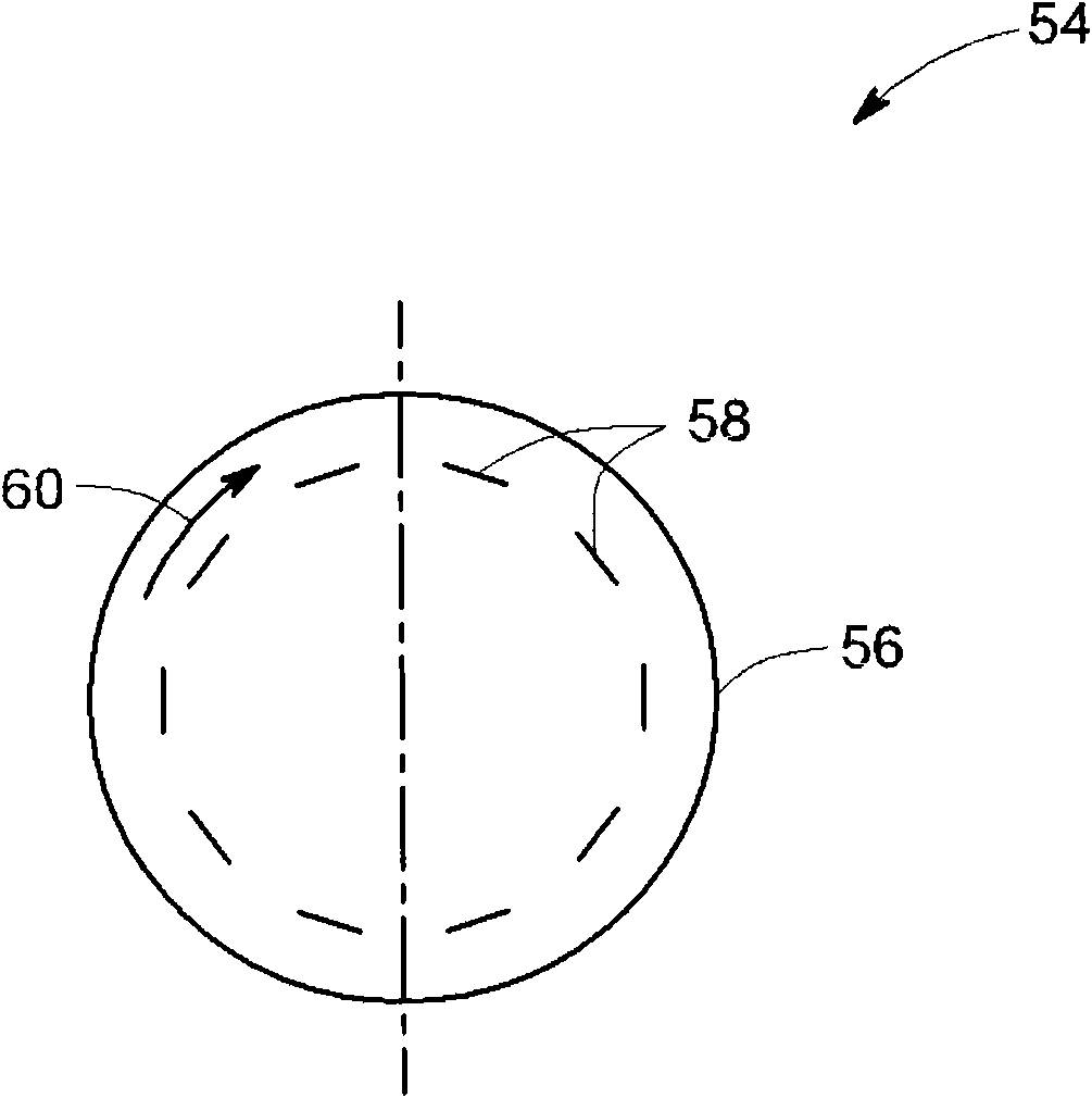
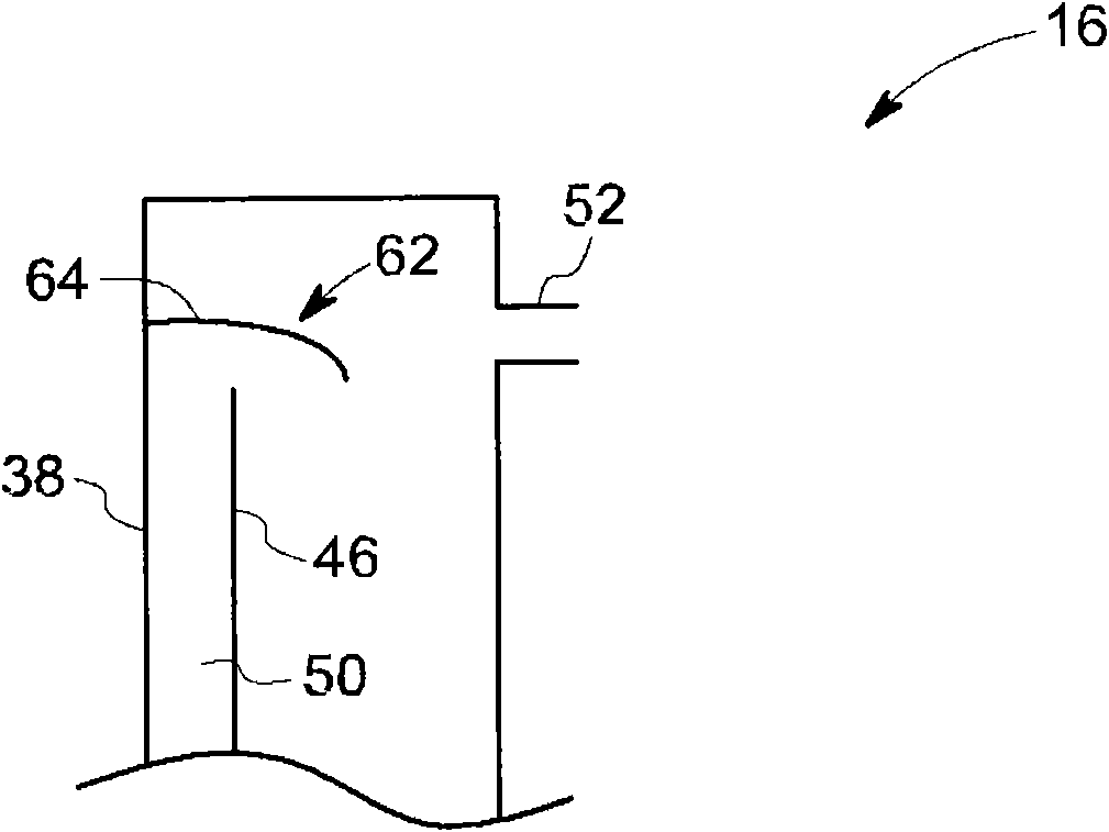
[0094] According to exemplary embodiments disclosed herein, a gasifier having a cooling chamber assembly configured to reduce the temperature of syngas downstream of a combustor is disclosed. The gasifier includes a cooling chamber containing a liquid coolant disposed downstream of the combustion chamber. Syngas produced from the combustor is directed through a dip tube to the cooling chamber to contact a liquid coolant and produce cooled syngas. The gasifier also includes a dip tube coupling the combustor to the cooling chamber and configured to direct syngas from the combustor to the cooling chamber to contact the liquid coolant and produce cooled syngas. The draft tube is arranged to surround the dip tube and define an annular passage therebetween. A liquid separator is disposed adjacent the outlet path of the cooling chamber and is configured to remove entrained liquid content from the cooled syngas channeled to the outlet path through the annular passage. In one embodim...


PUM


Abstract

The invention relates to a cooling chamber assembly for a gasifier. A gasifier includes a combustion chamber in which a combustible fuel is burned to produce a syngas and a particulated solid residue. A cooling chamber having a liquid coolant is disposed downstream of the combustion chamber. A dip tube is disposed coupling the combustion chamber to the cooling chamber. The syngas is directed from the combustion chamber to the cooling chamber via the dip tube to contact the liquid coolant and produce a cooled syngas. An asymmetric or symmetric liquid separator is disposed proximate to an exit path of the cooling chamber and configured to remove entrained liquid content from the cooled syngas directed through the annular passage to the exit path.

Description

technical field [0001] The present invention relates generally to gasifiers, and more particularly to cooling chamber assemblies for gasifiers. Background technique [0002] In a common coal gasification process in which a particulate carbonaceous fuel such as coal or coke or a carbonaceous gas is combusted, the process is carried out at relatively hot temperatures and high pressures in a combustion chamber. When the injected fuel is combusted or partially combusted in the combustion chamber, the effluent is discharged through a port at the lower end of the combustion chamber to a cooling chamber disposed downstream of the combustion chamber. The cooling chamber contains a liquid coolant, such as water. The effluent from the combustion chamber is contacted with liquid coolant in the cooling chamber to reduce the temperature of the effluent. In some applications, the cooling chamber can be used as a chill chamber for the syngas. In certain other applications, the cooling c...

Claims


Application Information

Patent Timeline
Patent Type & Authority Applications(China)
IPC IPC(8): C10J3/84C10J3/48
CPCC10J3/845C10J3/84Y02E20/18C10J3/485C10J3/526C10J3/74C10J3/76C10J2300/093C10J2300/0943C10J2300/0956C10J2300/0959B01D51/00C10J3/46F02C6/00F02C7/18F23D99/00F23J15/06F28C3/06
Inventor C·迪努J·B·科里J·M·斯托里D·M·里科R·L·赵
Owner GENERAL ELECTRIC CO
Why Eureka
Try Eureka