Adjustable water nozzle for oilfield water injection and water distributor with same

A technology for oil field water injection and water distributor, which is applied in the fields of production fluid, wellbore/well components, earth-moving drilling, etc. Good, simplified connection and meshing effect

Inactive Publication Date: 2011-01-05
SOUTHWEST PETROLEUM UNIV
View PDF5 Cites 10 Cited by
  • Summary
  • Abstract
  • Description
  • Claims
  • Application Information

AI Technical Summary

Problems solved by technology

The above-mentioned adjustable water nozzle is based on the improved design of the eccentric water injection plug in the oilfield. The adjustable water nozzle is set on the plug, and the plug is put into the designated working cylinder of the eccentric water injection well with a thrower, because The plug is arranged eccentrically, and the fluid flows from the high-pressure end of the faucet to the low-pressure end. To seal the faucet, the valve core of the faucet must move from the low-pressure end of the faucet to the high-pressure end, which coincides with the decrease of the pressure gradient. The small direction is opposite, and the pressure of the water flow has a negative effect on the sealing of the valve core, which also leads to the poor sealing of the plug-type adjustable faucet, the low pressure resistance, and the large driving torque required for adjusting the drive.
These adjustable water nozzles cannot meet the requirements of oilfield fine water injection in terms of deployment efficiency and water injection accuracy. Of course, the water distributors using these water nozzles cannot meet the requirements of fine water injection technology.

Method used


Image

  • Adjustable water nozzle for oilfield water injection and water distributor with same
  • Adjustable water nozzle for oilfield water injection and water distributor with same
  • Adjustable water nozzle for oilfield water injection and water distributor with same

Examples


Embodiment 1

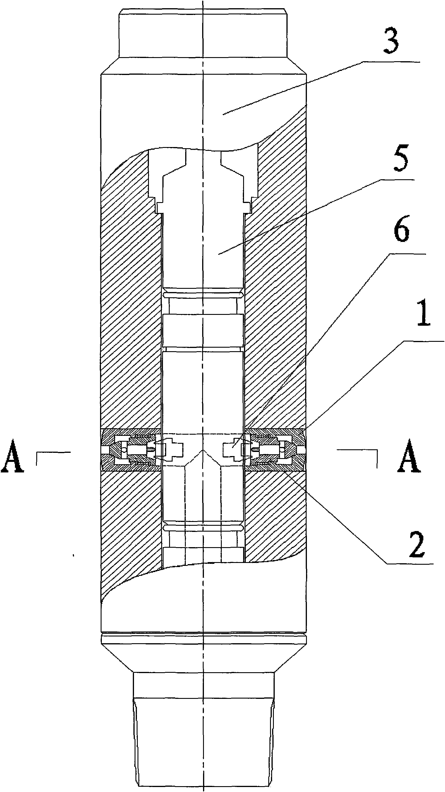
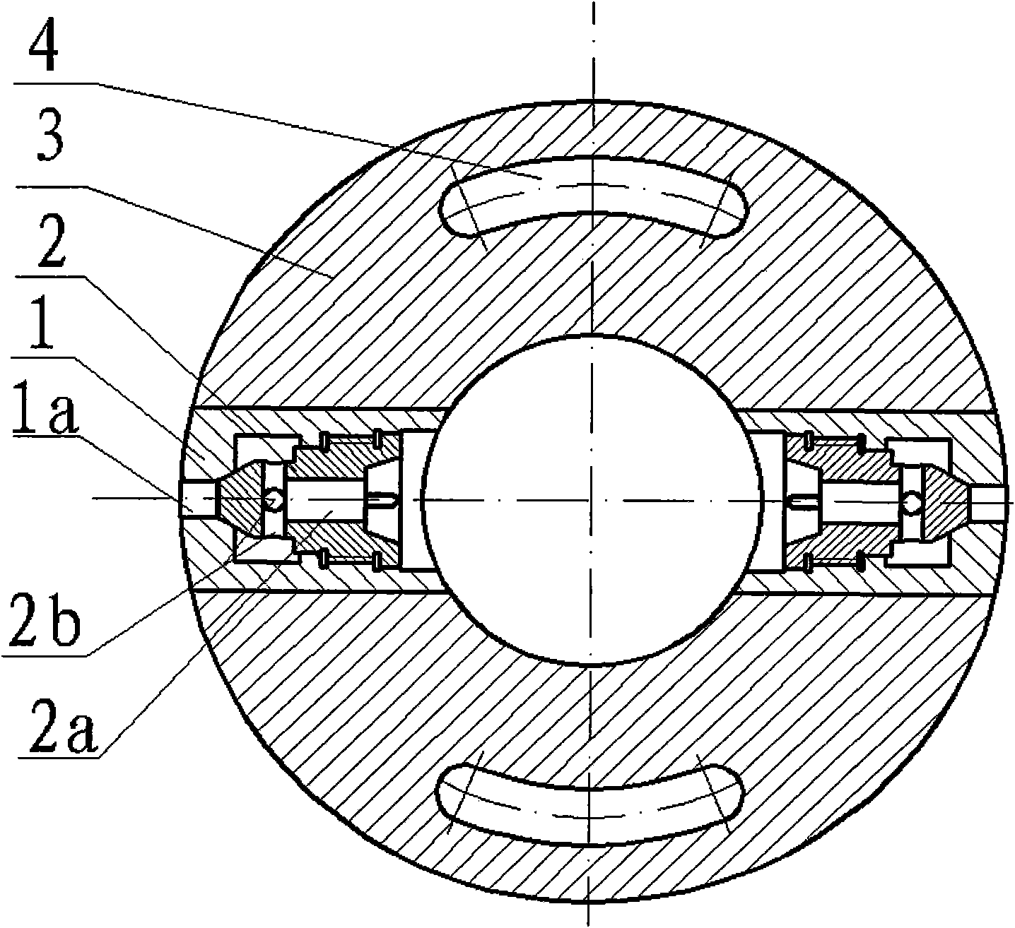
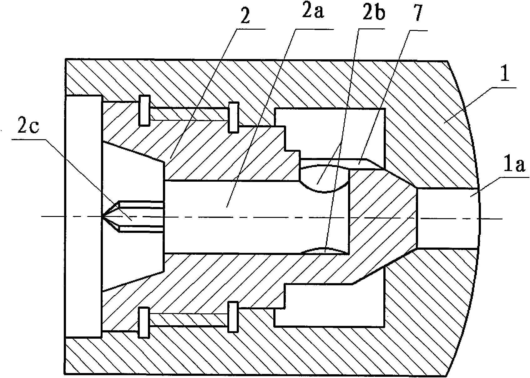
[0043] Example 1 as figure 1 , figure 2 , image 3 As shown, the adjustable nozzle for oilfield water injection of the present invention includes a valve sleeve 1 and a valve core 2 arranged in the valve sleeve 1. The valve sleeve is a cavity structure, and the outside of the valve core 2 is connected to the The inner wall is threadedly connected, the valve sleeve 1 is provided with a water outlet hole 1a, the head of the valve core 2 is in sealing fit with the taper surface of the valve sleeve 1 water outlet hole 1a, and the side of the valve core 2 head is provided with 3 A side hole 2b, a water inlet hole 2a is arranged in the valve core 2, and the water inlet hole 2a communicates with the three side holes 2b on the head of the valve core 2, and the head of the valve core 2 is provided with There is a diversion groove 7 connected to the side hole 2b, so that water injection can enter the cavity through the side hole 2b, and also easily enter the water outlet hole 1a thro...

Embodiment 2

[0044] Embodiment 2 is similar to Embodiment 1, and its difference is: described side hole 2b is 4, and 4 are evenly distributed with the head side of spool 2, and described water inlet hole 2a is 2, enters The water holes 2a are merged and distributed in the center of the valve core 2 and are separated from each other. The water inlet hole 2a communicates with all the side holes 2b. Groove 7, so that water injection can enter the cavity through side hole 2b, and also easily enter into water outlet hole 1a through diversion groove 7, playing the role of drainage. There are four claw petals 2c, and the cross section of the claw petals 2c is based on the center of the spool 2 as a sector shape with an included angle of 45°. The included angle between the end faces of the tail is 45°, the head of the valve core 2 is configured as a conical structure, and the outlet hole 1a of the valve sleeve 1 is configured as a conical structure corresponding to the conical structure of the hea...

Embodiment 3

[0045] Embodiment 3 is similar to Embodiment 1, and its difference is: described side hole 2b is 5, and 5 side holes 2b are evenly distributed on the head side of valve core 2, and described water inlet hole 2a is 3 One, the three water inlet holes 2a are combined and arranged at the center of the valve core 2, which are separated from each other, all the water inlet holes 2a communicate with all the side holes 2b, and the head of the valve core 2 is set There is a diversion groove 7 connected to the side hole 2b, so that water injection can enter the cavity through the side hole 2b, and also easily enter the water outlet hole 1a through the diversion groove 7, playing the role of drainage. There are 5 claw petals 2c, and the cross section of the claw petals 2c is based on the center of the valve core 2 as a sector shape with an included angle of 60°. The angle between the end faces of the tail is 60°, the head of the valve core 2 is configured as a conical structure, and the ...


PUM


Abstract

The invention discloses an adjustable water nozzle for oilfield water injection and a water distributor with the same, and belongs to the technical field of oilfield separate zone water injection. The adjustable water nozzle comprises a valve sleeve and a valve core, wherein the valve sleeve has a cavity structure and is provided with a water outlet hole; the valve sleeve is in threaded fit with the valve core; the valve core is in seal fit with the conical surface of the water outlet hole of the valve sleeve; the head of the valve core is provided with a side hole; a cavity is formed betweenthe valve sleeve and the valve core outside the side hole; a water inlet hole is formed in the valve core; and the tail part of the valve core is provided with a claw. The water distributor has a tube-shaped structure; the adjustable water nozzle is vertically arranged on the side of the water distributor and is communicated with the inner wall and the outer side of the water distributor; a bridge channel for water injection is formed in the wall of the water distributor; and a water nozzle adjuster for controlling the adjustable water nozzle is arranged in the water distributor. The adjustable water nozzle and the water distributor can accurately control water injection rate and are suitable to be popularized in the technical field of the oilfield separate zone water injection.

Description

technical field [0001] The invention relates to a layered water injection technology for an oil field, in particular to a fine layered water injection device for an oil field. Background technique [0002] At present, with the shortage of crude oil in the world, people pay more and more attention to how to improve the oil recovery rate of developed oilfields. Oilfield layered water injection is a common method in the process of oilfield exploitation, and it is widely used in the world. [0003] The eccentric layered water distribution method is commonly used in the water injection process of oilfields in my country. First, according to the theoretical water distribution and actual water distribution of each oil layer and the nozzle loss curve, a water nozzle with a fixed size is roughly selected and put into the plug. , put the plug into the designated work cylinder of the eccentric water injection well with a dropper, and then use a flowmeter to test the actual water injecti...

Claims


Application Information

Patent Timeline
Patent Type & Authority Applications(China)
IPC IPC(8): E21B43/20
Inventor 刘清友王国荣黎伟
Owner SOUTHWEST PETROLEUM UNIV
Why Eureka
Try Eureka