Electromechanical intelligent anti-theft lock trinity key
An anti-theft lock and intelligent technology, applied in the direction of keys, electric registration locks, building locks, etc., can solve the problems of convenient use, performance limitations, no remote control recognition function, and difficult to manufacture, so as to achieve strong anti-decoding ability and improve security. and reliability, powerful effect
- Summary
- Abstract
- Description
- Claims
- Application Information
AI Technical Summary
Problems solved by technology
Method used
Image
Examples
Embodiment 1
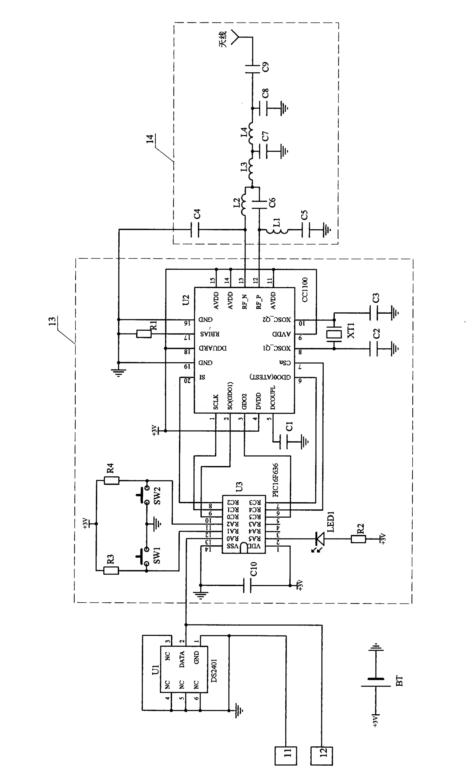
[0054] Embodiment one: see figure 1 , Figure 3 to Figure 10 , in the figure, the electromechanical intelligent anti-theft lock key control circuit contains 1-Wire Type electronic registration code memory U1, wireless transceiver control module 13, wireless transceiver driver module 14 and battery BT, 1-Wire The data port DATA of type electronic registration code memory U1 is connected with wireless transceiver control module 13, and the input / output end of wireless transceiver control module 13 is connected with the input / output end of wireless transceiver drive module 14, and battery BT is wireless transceiver control module 13 and The wireless transceiver driver module 14 provides power. 1-Wire The model of electronic registration code memory U1 is DS2401.
[0055] Wireless transceiver control module 13 contains microprocessor U3, RF transceiver U2 and button SW1, SW2, 1-Wire The data port DATA of the electronic registration code memory U1 is connected to the input...
Embodiment 2
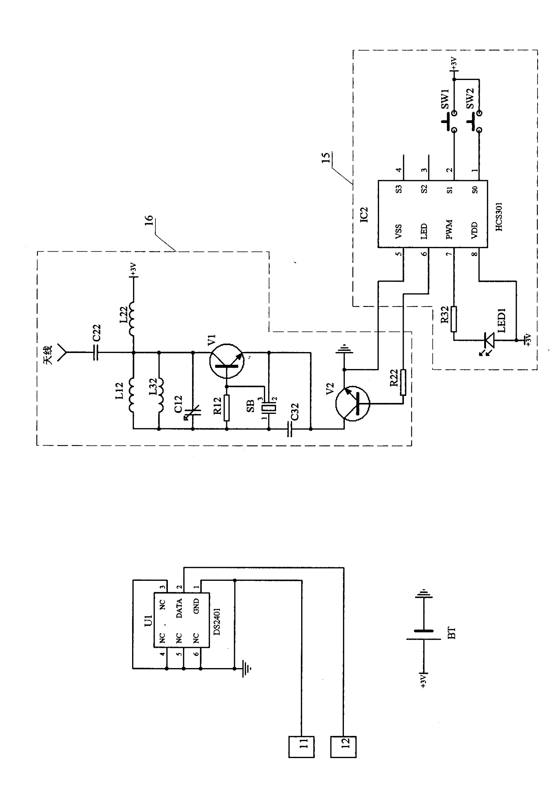
[0060] Embodiment two: see Figure 2 to Figure 10 , the number in the figure is the same as that of Embodiment 1, the representative meaning is the same, and its working process is basically the same, and the similarities will not be repeated. The difference is: the electromechanical intelligent anti-theft lock key control circuit contains 1-Wire Type electronic registration code memory U1, wireless transceiver control module 15, wireless transceiver driver module 16 and battery BT, 1-Wire Type electronic registration code memory U1 is an independent part, it is not connected with other parts, the input / output end of wireless transceiver control module 15 is connected with the input / output end of wireless transceiver drive module 16, battery BT is wireless transceiver control module 15 and The wireless transceiver driver module 16 provides power. 1-Wire The model of electronic registration code memory U1 is DS2401.
[0061] The wireless transceiver control module 15 cont...
Embodiment 3
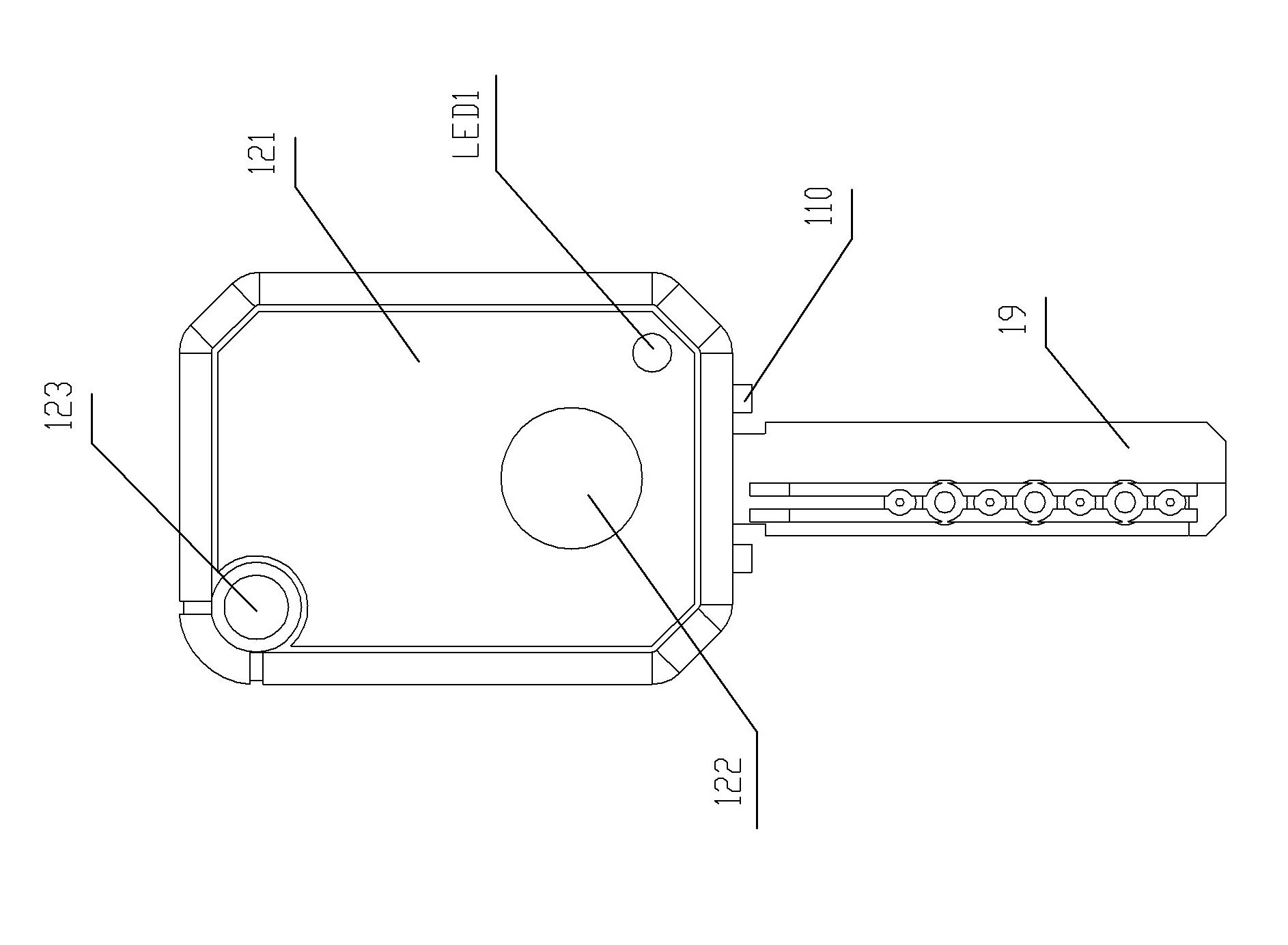
[0063] Embodiment three: see figure 1 , Figure 11 ~ Figure 22 , the numbers in the figure are the same as those in Embodiment 1, the representative meanings are the same, and the working process is basically the same, and the similarities will not be repeated. The key control circuit, the insulating fixture handle with control key, the conductor key plug 19 and the electrode contact body 110 insulated from one end of the conductor key plug 19, the circuit board 111 that contains the control circuit of the electronic key is mounted on the insulation with the control key. In the inner cavity of the handle of the fixed frame, the circuit board 111 contains a data port 12 and a grounding port 11, and the data port 12 is connected to the 1-Wire in the electromechanical intelligent anti-theft lock key control circuit. The data port DATA of the type electronic registration code memory U1 is connected, and the grounding port 11 is connected with the 1-Wire in the electronic key contr...
PUM
 Abstract
Description
Claims
Application Information
 - R&D
- Intellectual Property
- Life Sciences
- Materials
- Tech Scout
- Unparalleled Data Quality
- Higher Quality Content
- 60% Fewer Hallucinations
Browse by: Latest US Patents, China's latest patents, Technical Efficacy Thesaurus, Application Domain, Technology Topic, Popular Technical Reports.
© 2025 PatSnap. All rights reserved.Legal|Privacy policy|Modern Slavery Act Transparency Statement|Sitemap|About US| Contact US: help@patsnap.com


