Camera-equipment-array based dynamic scene depth restoring method

A dynamic scene, depth recovery technology, applied in the field of computer vision, can solve the problems of time consistent constraint effects, spatiotemporal optimization effects need to be improved, spatial consistency constraints and time consistent constraints are not uniform in form, to achieve the effect of ensuring stability

Active Publication Date: 2011-01-12
TSINGHUA UNIV
View PDF5 Cites 10 Cited by
  • Summary
  • Abstract
  • Description
  • Claims
  • Application Information

AI Technical Summary

Problems solved by technology

[0006] 1) The form of space-consistency constraints and time-consistency constraints is not uniform, and the effect of space-time optimization still needs to be improved;
[0007] 2) When the motion estimation is wrong, it will have a negative impact on the temporal consistency constraints;
[0008] 3) Some algorithms are only applicable to fixed cameras, and can only be solved at each moment when the camera is moving

Method used


Image

  • Camera-equipment-array based dynamic scene depth restoring method
  • Camera-equipment-array based dynamic scene depth restoring method
  • Camera-equipment-array based dynamic scene depth restoring method

Examples


Embodiment Construction

[0021] Embodiments of the present invention are described in detail below, examples of which are shown in the drawings, wherein the same or similar reference numerals designate the same or similar elements or elements having the same or similar functions throughout. The embodiments described below by referring to the figures are exemplary only for explaining the present invention and should not be construed as limiting the present invention.

[0022] The present invention mainly lies in that the stability of the depth map sequence of each camera can be effectively ensured through uniform space-time and space-time constraints, and at the same time, multi-time depth information is used to correct single-time errors.

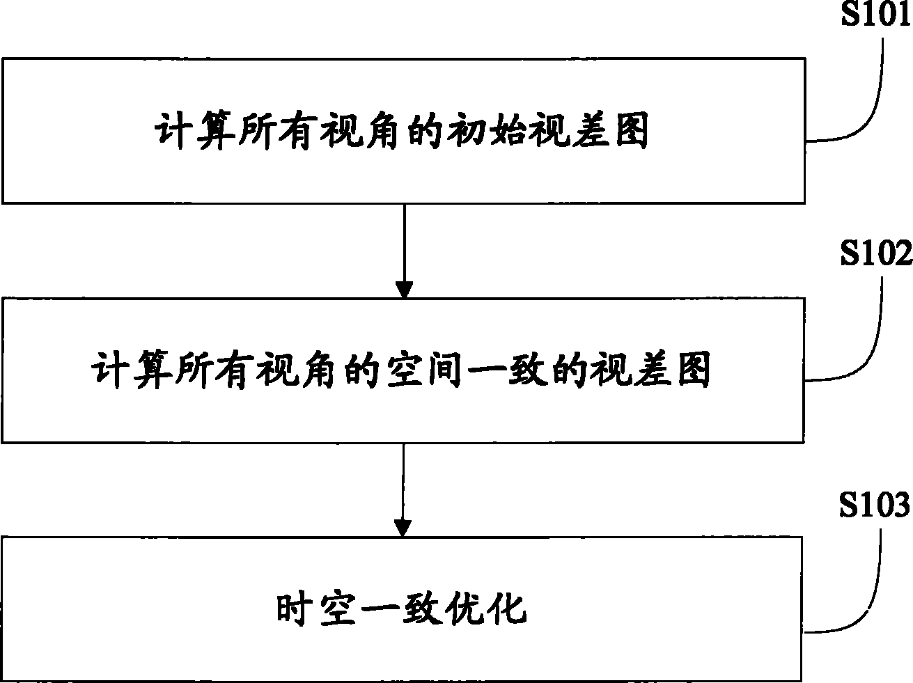
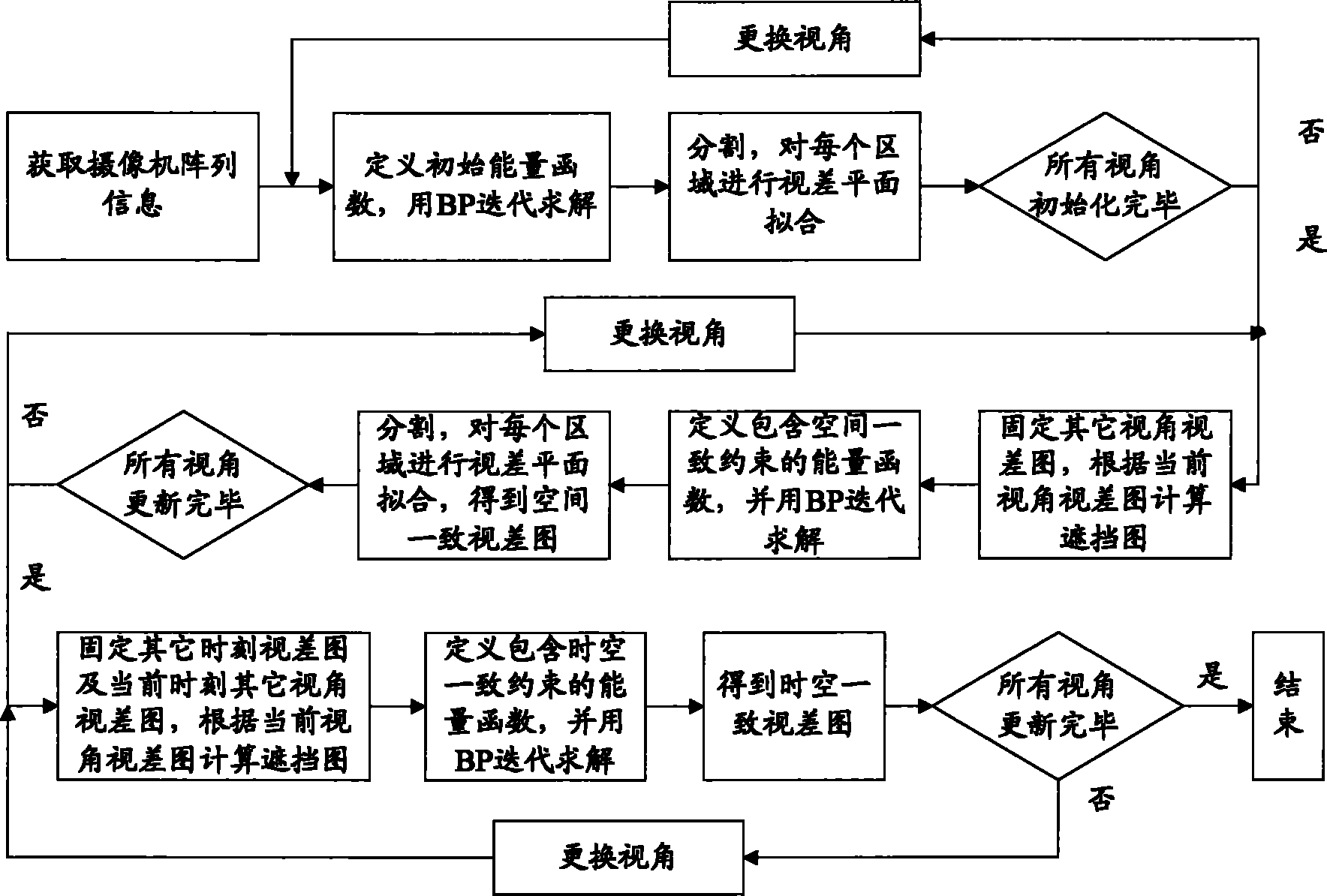
[0023] In order to achieve the above object, an embodiment of the present invention proposes a dynamic scene depth restoration method based on a photographing device array. figure 1 A flow chart of the above-mentioned dynamic scene depth restoration method is shown...


PUM


Abstract

The invention provides a camera-equipment-array based dynamic scene depth restoring method, which comprises the following steps of: initializing parallax graphs to acquire initial parallax graphs of all visual angles at the t moment; performing the optimization of space consistency on the initial parallax graphs of all visual angles at the t moment to obtain parallax graphs, with the consistent space, of all visual angles at the t moment; and performing the optimization of space-time consistency to restore the parallax graphs of the dynamic scene. In the method, the stability of a deep graph sequence of each camera can be ensured effectively through space consistent constraint and space-time consistent constraint which have a uniform form, and simultaneously, the correction of single-moment error is performed by utilizing multi-moment depth information.

Description

technical field [0001] The invention relates to the field of computer vision, in particular to a dynamic scene depth recovery method based on a shooting device array. Background technique [0002] The camera array is formed by a group of cameras (that is, multiple cameras) arranged in a certain way, such as linear arrangement, planar arrangement or circular arrangement. The work carried out on this basis usually requires geometric calibration and color calibration of each camera first. Through geometric calibration, the internal parameter matrix K and external parameter matrix of each camera can be obtained. The external parameter matrix includes a rotation matrix R and a translation vector T. Through color calibration, the collected sample color can be as close as possible to the target color. [0003] As a basic problem in computer vision, stereo matching has been a research hotspot for decades. Its research content is how to obtain a high-quality depth map, which is t...

Claims


Application Information

Patent Timeline
Patent Type & Authority Applications(China)
IPC IPC(8): H04N13/00
Inventor 季向阳杨明进戴琼海
Owner TSINGHUA UNIV
Why Eureka
Try Eureka