Device for the automatic suction power regulation of a vacuum cleaner

An automatic adjustment and vacuum cleaner technology, which is applied in the installation of vacuum cleaners, vacuum cleaner equipment, and electrical equipment, and can solve problems such as increased sliding resistance of suction nozzles

Inactive Publication Date: 2011-01-12
BSH BOSCH & SIEMENS HAUSGERAETE GMBH
View PDF4 Cites 19 Cited by
  • Summary
  • Abstract
  • Description
  • Claims
  • Application Information

AI Technical Summary

Problems solved by technology

The disadvantage of this control mechanism is that the sliding resistance of the suction nozzle increases significantly when changing from a smooth floor to a soft floor covering

Method used


Image

  • Device for the automatic suction power regulation of a vacuum cleaner
  • Device for the automatic suction power regulation of a vacuum cleaner
  • Device for the automatic suction power regulation of a vacuum cleaner

Examples


Embodiment Construction

[0027] In the following description of the preferred embodiments of the present invention, the same reference numerals denote the same or similar components.

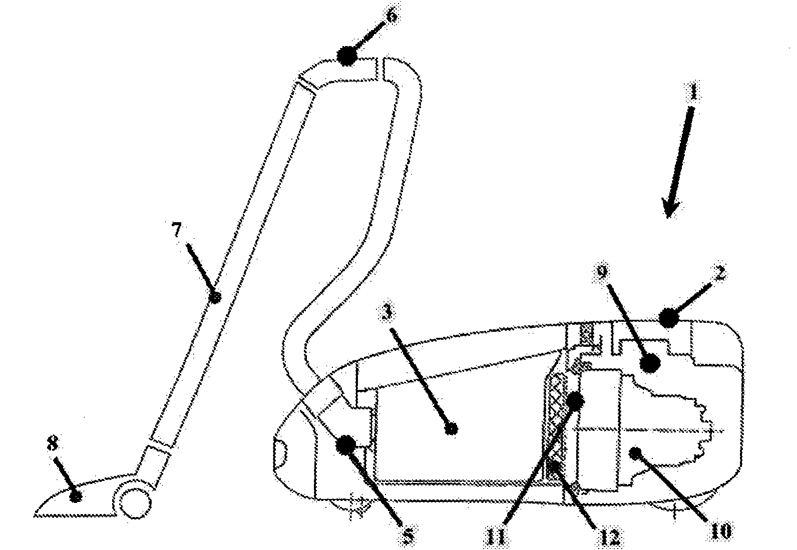
[0028] figure 1 A vacuum cleaner 1, in this case a floor vacuum cleaner, is schematically shown, comprising a vacuum cleaner housing 2 and a dust separation unit 3 housed in the vacuum cleaner housing, which is located in the suction air flow 4 and is connected via a pipe connection 5 and a suction hose with a handle 6. The pipe is connected to the suction nozzle 8 through a connecting pipe 7 with variable length. A motor / fan unit 10 is provided in the motor / fan compartment 9 , and a motor protection filter 12 is usually provided before the motor / fan unit 10 in the motor / fan compartment.

[0029] The dust separation unit 3 is represented in this description not only as a known dust filter bag, but also as a so-called bagless unit. The fine dust contained in the suction action gradually blocks or closes the pores of th...


PUM


Abstract

The invention relates to a device for a vacuum cleaner (1). Said device only supplies as much electrical power to the motor / fan unit (10) as is necessary for the optimal cleaning of the floor surface to be cleaned and required by the respective operating states of the vacuum cleaner (1), thereby ensuring an energy-efficient use of the vacuum cleaner. Said device thereby ensures a constant cleaning action over the usable life of the vacuum cleaner (1). As the suction nozzle has a constant suction power, dust and dirt particles are always sucked up with a consistently applied suction power and supplied to a dust collection unit (3). The invention also protects the surfaces to be cleaned from being subjected to too much cleaning.

Description

technical field [0001] The invention relates to a device for automatically adjusting the suction power of a vacuum cleaner, the motor / fan unit of which is driven by a corresponding electric or electronic control circuit, and a dust suction nozzle is provided in front of the dust separation unit. Background technique [0002] In many known vacuum cleaners, a loss of suction power caused, for example, by clogging of the filter bag holes of the vacuum cleaner requires a manual or manual readjustment of the suction power, whereby an upward adjustment and thus a loss of energy are often associated. Known control mechanisms are currently under consideration: [0003] EP 0678271B1 discloses, for example, a circuit arrangement for the regulation of the suction power of a vacuum cleaner, the fan motor of which is equipped with a semiconductor switching element controllable by means of a control circuit, in which circuit arrangement the control circuit comprises a comparator, periodic...

Claims


Application Information

Patent Timeline
Patent Type & Authority Applications(China)
IPC IPC(8): A47L9/28
CPCA47L9/2842Y02B40/82A47L9/2821Y02B40/00
Inventor S·哈姆R·赫尔曼R·伊利希P·莱曼T·斯特雷勒
Owner BSH BOSCH & SIEMENS HAUSGERAETE GMBH
Why Eureka
Try Eureka