A lightweight AC contactor iron core and its manufacturing method
A technology of AC contactors and manufacturing methods, which is applied in the direction of inductance/transformer/magnet manufacturing, relays, electromagnetic relays, etc., can solve the problems of not being able to optimize the operating efficiency and manufacturing costs of contactors, and achieve the goal of reducing dirt. Opportunity, increase the integrity and structural strength, the effect of convenient processing
- Summary
- Abstract
- Description
- Claims
- Application Information
AI Technical Summary
Problems solved by technology
Method used
Image
Examples
Embodiment 1
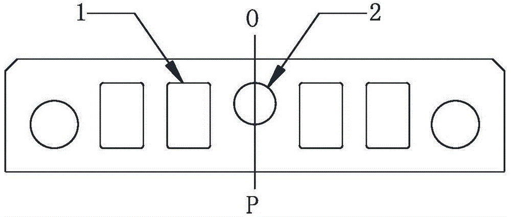
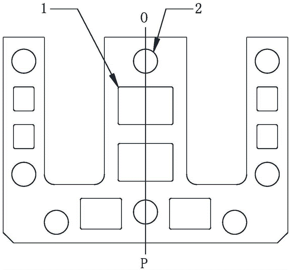
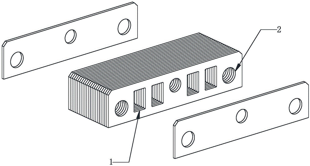
[0043] The iron core in this example is an E-type iron core. Both the moving iron core and the static iron core are composed of stacked silicon steel sheets. The structure of the moving iron core silicon steel sheets is as follows: figure 1 As shown, the structure of the static iron core silicon steel sheet is as follows figure 2As shown, OP is the symmetry axis of the silicon steel sheet. The circular through hole 2 in the figure is the assembly hole of the iron core, including the rivet hole for riveting the iron core and the bracket hole for installing the bracket. The rectangular through hole 1 in the figure is a hollow structure processed for weight reduction. Obviously, the hollow structure 1 can also be processed into a circular through hole. Although the weight reduction effect of the circular through hole is not as good as that of the rectangular through hole, the processing of the circular through hole is more convenient and the mold structure is simpler.
[0044]...
Embodiment 2
[0046] The iron core in this example is also an E-shaped iron core with a symmetrical structure, and the silicon steel sheet structure of the moving iron core is as follows: Figure 5 As shown, the structure of the static iron core silicon steel sheet is as follows Figure 6 shown. If one side of the silicon steel sheet is defined as the front side (side A), the opposite side is the back side (side B). see Figure 5 and Figure 6 ,in Figure 5 a is the front view of side A of the moving iron core silicon steel sheet, Figure 5 b is the front view of the B side of the moving iron core silicon steel sheet, Figure 6 a is the front view of surface A of the static iron core silicon steel sheet, Figure 6 b is the front view of the B side of the static iron core silicon steel sheet. It can be seen that in the iron core of this example, the hollow structures on the silicon steel sheets are located on both sides of the symmetry axis of the silicon steel sheets, and the positio...
PUM
 Abstract
Description
Claims
Application Information
 - R&D
- Intellectual Property
- Life Sciences
- Materials
- Tech Scout
- Unparalleled Data Quality
- Higher Quality Content
- 60% Fewer Hallucinations
Browse by: Latest US Patents, China's latest patents, Technical Efficacy Thesaurus, Application Domain, Technology Topic, Popular Technical Reports.
© 2025 PatSnap. All rights reserved.Legal|Privacy policy|Modern Slavery Act Transparency Statement|Sitemap|About US| Contact US: help@patsnap.com


