Rapid tool changing mechanical arm with electric drive pusher

A technology of electric push rod and electric push rod, which is applied to metal processing mechanical parts, clamping, support and other directions, can solve the problems of high structural complexity, low reliability, not suitable for high-speed tool change, etc., and achieves reliable driving and installation. The effect of small maintenance workload and simple structure

Inactive Publication Date: 2011-01-19
NANJING UNIV OF AERONAUTICS & ASTRONAUTICS +1
View PDF5 Cites 8 Cited by
  • Summary
  • Abstract
  • Description
  • Claims
  • Application Information

AI Technical Summary

Problems solved by technology

[0003] Aiming at the problems existing in the hydraulic power system of the existing tool changing manipulator, in order to overcome the shortcomings of the hydraulic power system of the tool changing manipulator, such as high structural complexity, low reliability, and inability to adapt to high-speed tool changing, the patent of the present invention proposes an electric Push rod tool changer

Method used


Image

  • Rapid tool changing mechanical arm with electric drive pusher
  • Rapid tool changing mechanical arm with electric drive pusher

Examples


Embodiment Construction

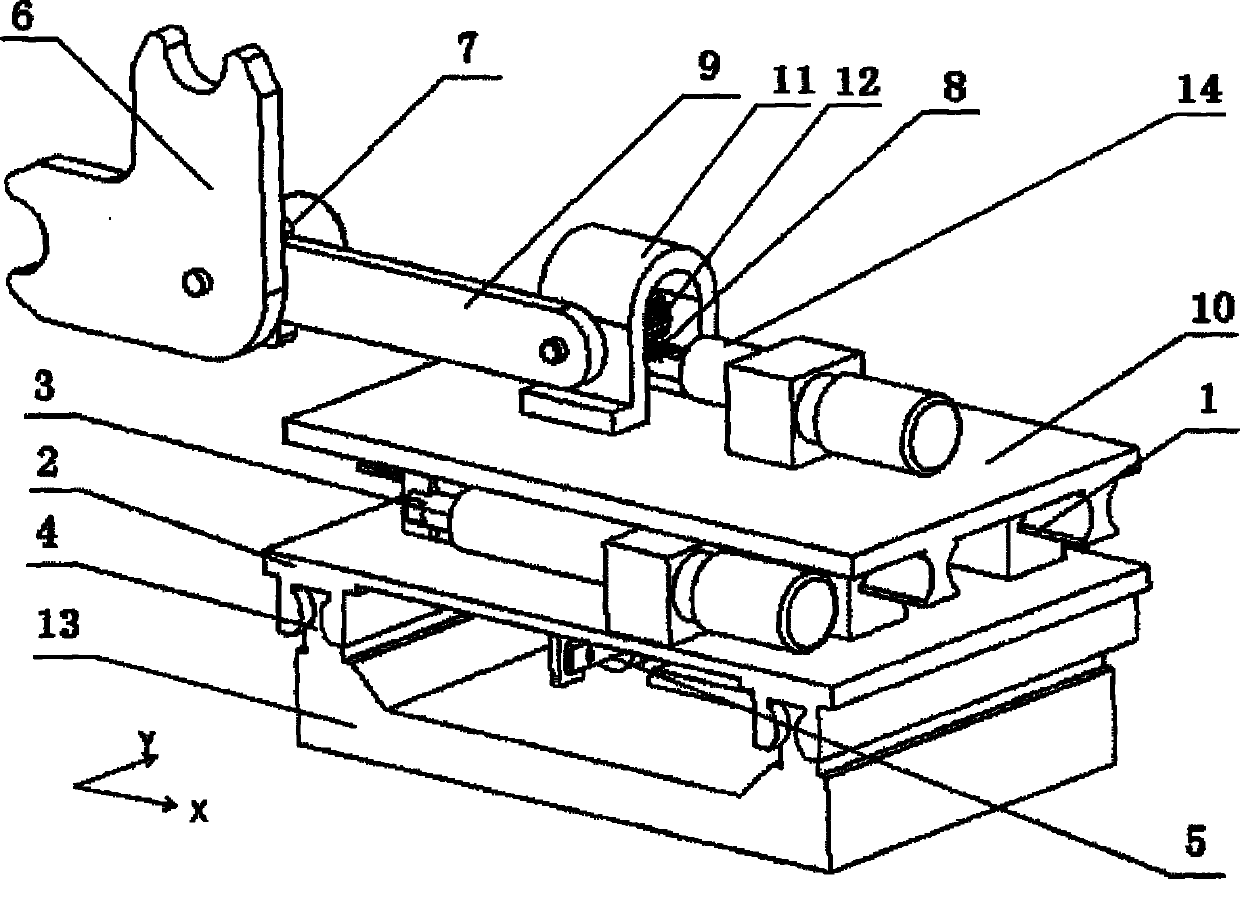
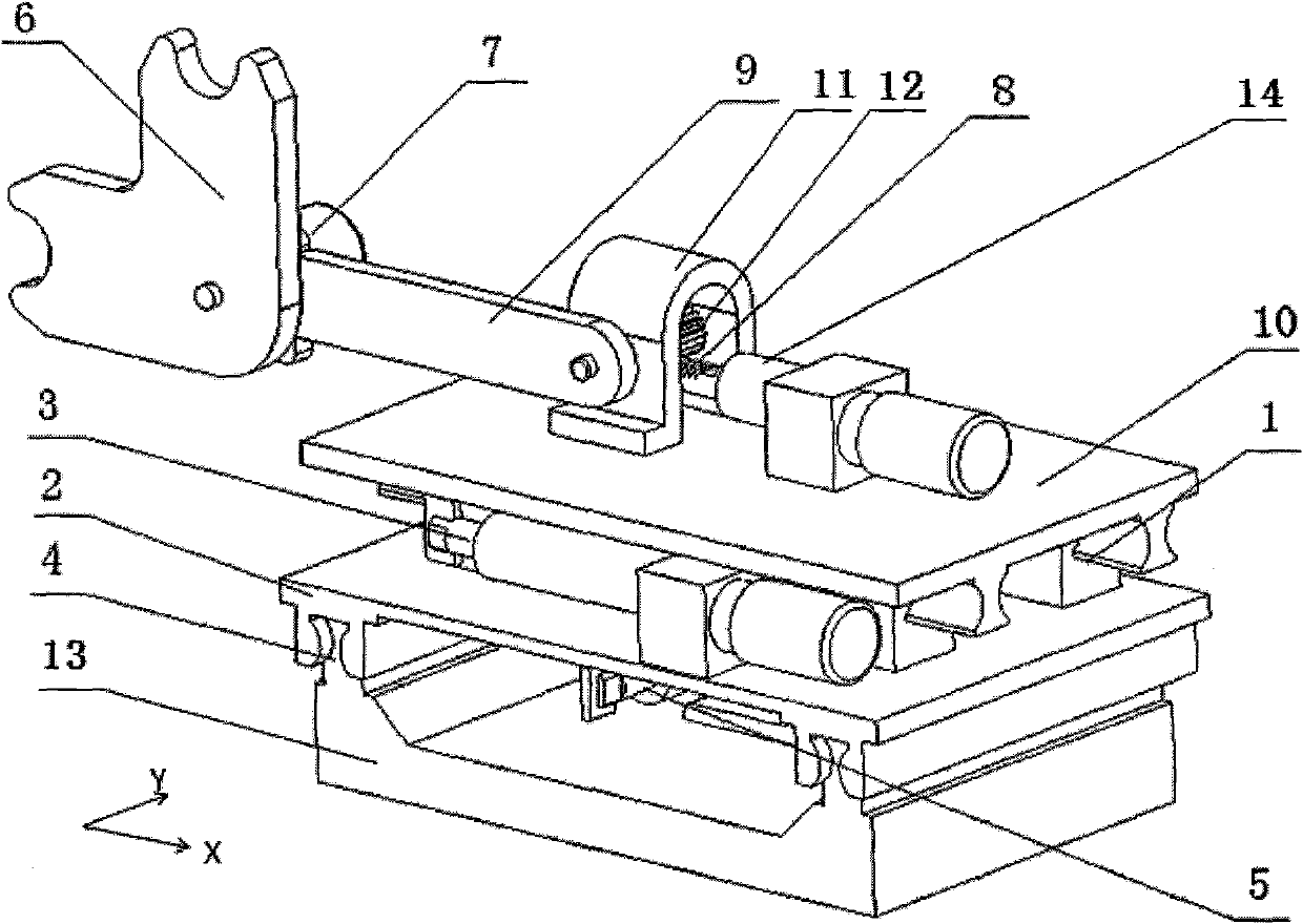
[0008] The present invention will be described in further detail below in conjunction with the accompanying drawings and specific embodiments.

[0009] The structure of the structure of the manipulator tool changing mechanism is as shown in the accompanying drawings. It is characterized in that it includes a manipulator swinging device composed of a third motor push rod 14, a gear 12 and a rack 8. The manipulator swinging device is realized by opening a rack on the electric push rod through a rack and pinion structure. The manipulator swing device is installed on the second linear guide pair 1 (that is, the X-axis linear guide pair) through the second sliding seat 10, and is connected with the second electric push rod 3 installed on the first sliding seat 2. The first sliding seat 2 Installed on the first linear guide pair 4 (that is, the Y-axis linear guide pair), and connected with the first electric push rod 5: the manipulator swing device includes a manipulator 6, which ca...


PUM


Abstract

The invention relates to a rapid tool changing mechanical arm with an electric drive pusher, belonging to the technical field of numerical control machine tool changing machine. The mechanical arm comprises a pedestal (13), a first linear guide rail pair (4), a first slide seat (2), a second linear guide rail pair (1), a second slide seat (10), a first electric drive pusher (5) arranged on the pedestal and with a displacement output terminal connected with a first slide seat and a second electric drive pusher (3) arranged on the first slide seat and with the displacement output terminal connected with the second slide seat. The second slide seat (10) is also provided with a swing arm support (11) and a third electric drive pusher (14), the swing arm support is provided with a swing arm (9), the tail end of the swing arm is provided with a tool-catching disk (6), the tool-catching disk (6) is connected with the output shaft of an electrical machine (7), a swing joint of the swing arm is provided with a gear (12), and the displacement output terminal of the third electric pusher is connected with a gear rack (8) matched with the gear. The invention features simple structure, high reliability, rapid and easily controlled motion.

Description

technical field [0001] The invention relates to a tool-changing manipulator of a numerically controlled machine tool, in particular to a fast tool-changing manipulator of a numerically controlled machine tool using an electric push rod. Background technique [0002] At present, hydraulic power components are generally used in the driving components of tool changing manipulators of CNC machine tools. Hydraulic power components can not only provide sufficient driving force, but also have mature technology and wide application. However, since the hydraulic power components are composed of oil pumps, pipelines and various valves, the whole system is relatively complicated. Therefore, on the one hand, the overall reliability of the hydraulic power components is not high, resulting in high maintenance costs; on the other hand, in the narrow space inside the CNC machine tool, it is difficult to install and maintain the hydraulic components of the tool changing manipulator. These ...

Claims


Application Information

Patent Timeline
Patent Type & Authority Applications(China)
IPC IPC(8): B23Q3/155
Inventor 臧铁钢叶文华凌卫国楼佩煌陈蔚芳
Owner NANJING UNIV OF AERONAUTICS & ASTRONAUTICS
Why Eureka
Try Eureka