Layer stranded optical cable, preparation method thereof and device for method

A layer-twisted, optical cable technology, applied in the direction of fiber mechanical structure, etc., can solve the problems of cost increase, water infiltration, damage to optical cable performance, etc., and achieve the effect of simple structure, good combination, and avoiding longitudinal water seepage

Inactive Publication Date: 2011-01-19
YANGTZE ZHONGLI OPTICAL FIBER & CABLE (JIANGSU) CO LTD
View PDF24 Cites 47 Cited by
  • Summary
  • Abstract
  • Description
  • Claims
  • Application Information

AI Technical Summary

Problems solved by technology

However, steel wire manufacturers usually apply a layer of grease on the outside of the steel wire in order to prevent the steel wire from rusting, and when the optical cable manufacturer squeezes the plastic cushion on the steel wire coated with grease, in order to ensure the bonding effect between the plastic cushion and the steel wire, To avoid water seepage in the longitudinal direction, an open flame is usually used to burn off the grease coated on the outside of the steel wire. This method obviously has the problem of taking care of one thing and losing the other. To a certain extent, the steel wire and the plastic cushion will not slide relative to each other, and the water resistance is ideal; the so-called loss means that after the grease is removed, the anti-rust effect of the steel wire will be seriously affected, and the use of an open flame to remove the grease will affect the environment. , and there are unsafe hidden dangers. Although using chemical methods such as using a degreasing agent to remove the grease outside the steel wire can avoid the unsafe hidden danger of burning the grease with an open fire (causing a fire), it will also cause the steel wire to rust, and the degreasing agent is used to remove the grease. Also environmentally unfavorable, in addition to increased process s

Method used


Image

  • Layer stranded optical cable, preparation method thereof and device for method
  • Layer stranded optical cable, preparation method thereof and device for method
  • Layer stranded optical cable, preparation method thereof and device for method

Examples


Embodiment 1

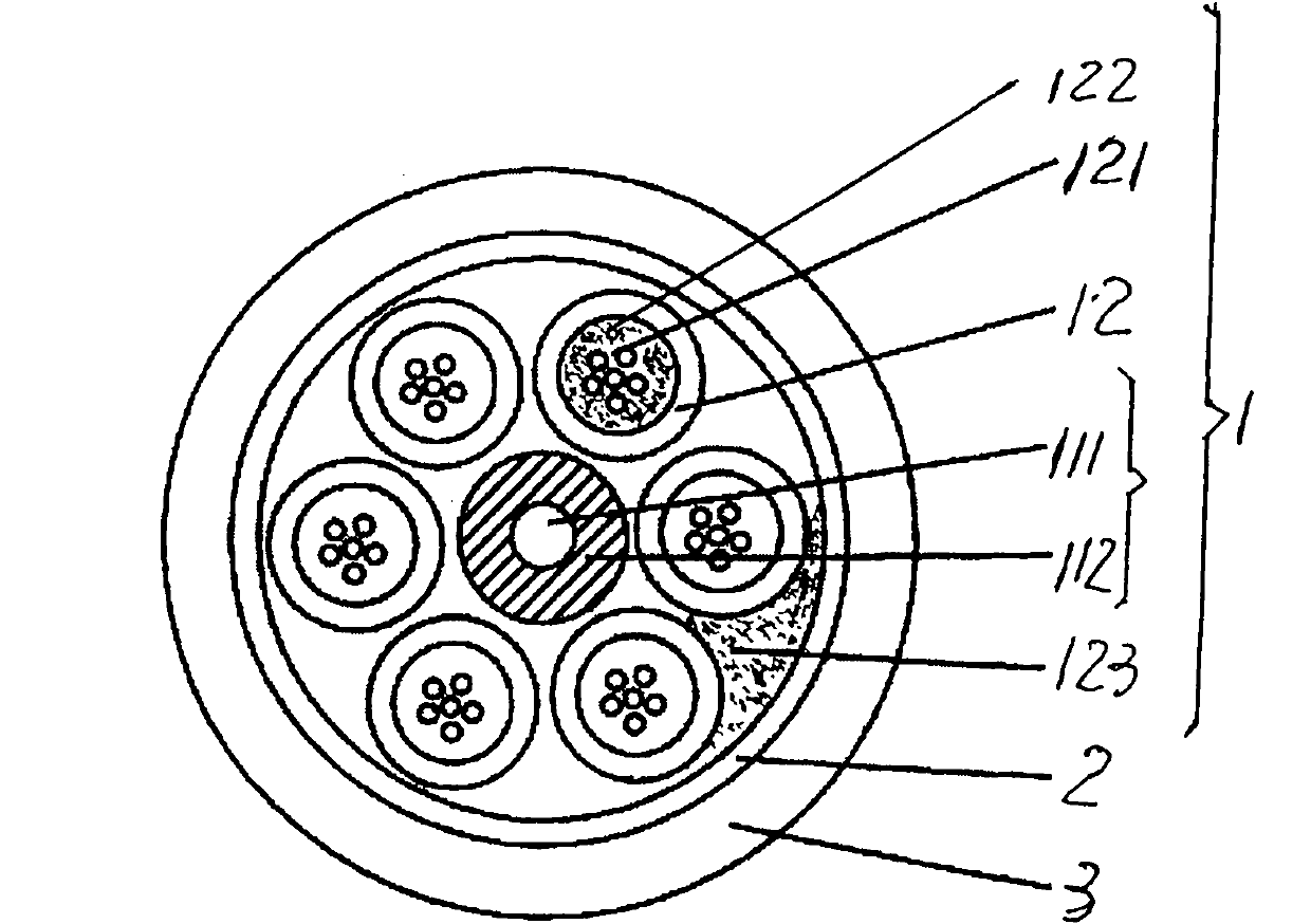
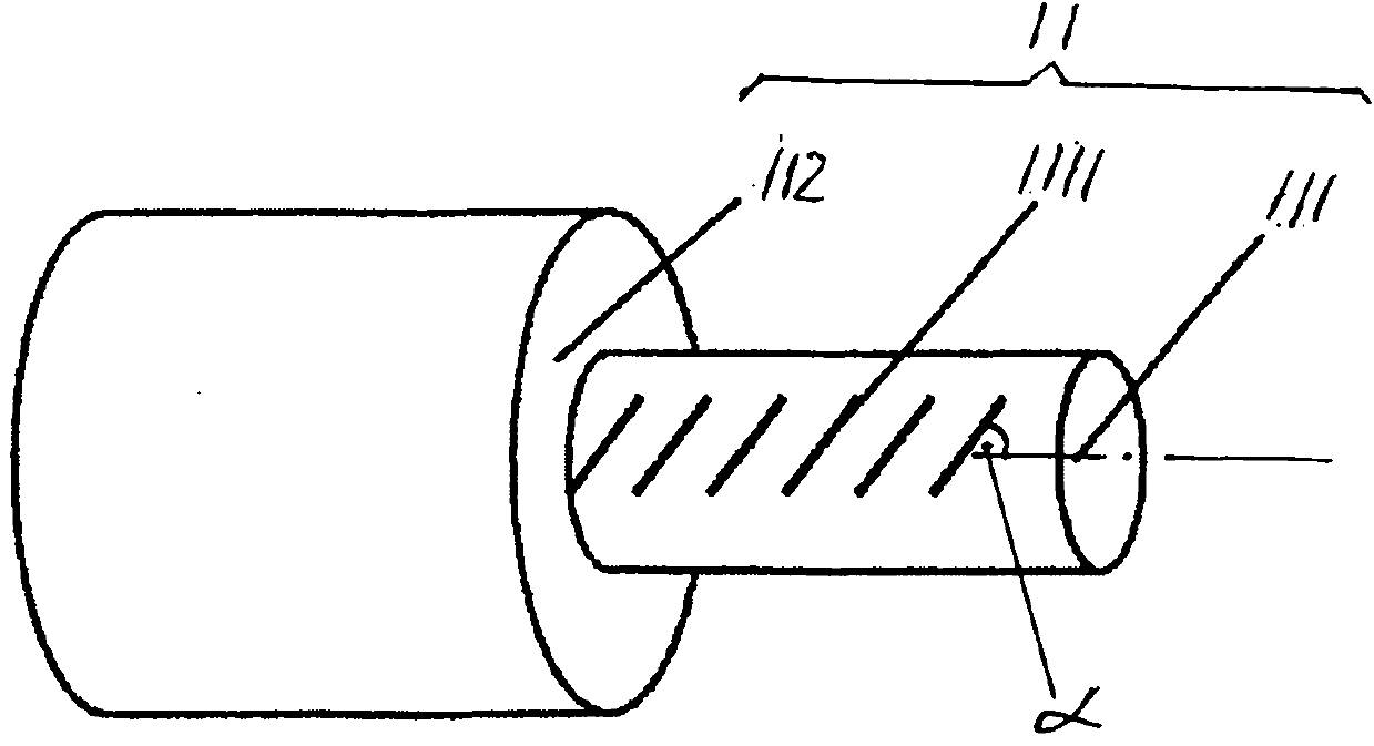
[0049] This example is for the preparation of figure 1 In terms of the layer twisted optical cable of the structure shown.

[0050] please see figure 1 , Figure 4 and Figure 6 , prepared by figure 1 The method for the layer twisted optical cable of the shown structure comprises the following steps:

[0051] A) Optical fiber coloring that will be used to accommodate the figure 1 As shown, the optical fibers 121 in the five loose tubes 12 that constitute the cable core 1 are introduced into the optical fiber coloring machine for coloring, and the outer surfaces of the optical fibers 121 are combined with identifiable colors to obtain colored optical fibers. Because in this embodiment, each There are six optical fibers 121 in each loose tube 12, and the cross-sectional shape of each optical fiber 121 is circular, therefore, six optical fibers 121 are colored into six different colors by an optical fiber coloring machine, and different colors can provide identification (ide...

Embodiment 2

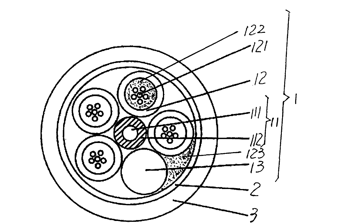
[0062] This example is for the preparation of figure 2 In terms of the layer twisted optical cable of the structure shown.

[0063] please see figure 2 , Figure 5 and Figure 7 , prepared by figure 2 The method for the layer twisted optical cable of the shown structure comprises the following steps:

[0064] A) Optical fiber coloring that will be used to accommodate the figure 2 As shown, the optical fibers 121 in the six loose tubes 12 that constitute the cable core 1 are introduced into the optical fiber coloring machine for coloring, and the outer surfaces of the optical fibers 121 are combined with identifiable colors to obtain colored optical fibers. Because in this embodiment, each There are six optical fibers 121 in each loose tube 12, and the cross-sectional shape of each optical fiber 121 is circular, therefore, six optical fibers 121 are colored into six different colors by an optical fiber coloring machine, and different colors can provide identification (...

Embodiment 3

[0071] sketches. Only change the quantity of the loose tube 12 described in step A) into three, and change the root number of the optical fiber 121 in each loose tube 12 into ten; change the diameter of the steel wire 111 in step C) into 2.1 mm, the depth of the groove 1111 is changed to 0.21 mm; the protective layer 2 in step E) is changed to a polyester film tape; the material of the sheath layer 3 in step F) is changed to low-smoke halogen-free flame-retardant polyethylene. All the other are the same as the description to embodiment 1.


PUM

PropertyMeasurementUnit
Depthaaaaaaaaaa
Angleaaaaaaaaaa
Diameteraaaaaaaaaa

Abstract

The invention relates to a layer stranded optical cable, a preparation method thereof and a device for the method, belonging to the technical field of optical fibers and optical cables. The layered stranded optical cable comprises a cable core, a protective layer coated outside the cable core and a jacket layer extruded and coated outside the protective layer, wherein the cable core comprises a central reinforcer and more than two loose casings twisted with the central reinforcer; the central reinforcer is formed by a steel wire coated with grease on the external wall and a plastic cushion layer extruded and coated outside the steel wire; and the loose casings respectively contain a plurality of optical fibers. The layered stranded optical cable is characterized in that a groove is formed on the external wall of the steel wire; and the plastic cushion layer is embedded into the groove. The invention can ensure that the fine combination of the plastic cushion layer and the steel wire can be guaranteed to avoid the longitudinal water seepage of the cable core under the premise that the grease coated outside the steel wire is not required to be eliminated; the groove is formed on the surface of the steel wire capable of forming the central reinforcer before entering a plastic extruding machine for the plastic cushion layer so that the plastic cushion layer is reliably combined with the steel wire by utilizing the groove; and an added steel wire grooving machine has simple structure and has no interference to other machinery.

Description

technical field [0001] The invention belongs to the technical field of optical fiber and cable, in particular relates to a layer-stranded optical cable, and also relates to a preparation method of the layer-stranded optical cable and a device used in the method. Background technique [0002] With the development of the communication industry, optical cables are widely used in the field of communication due to the large amount of information transmitted. There are roughly three types of optical cable structures used in the field of communication: one is the layer twisted optical cable; the second is the central beam tube optical cable; the third is the skeleton optical cable. [0003] The layered optical cable is to add the colored optical fiber and ointment to the loose tube made of high modulus plastic at the same time. Core) twisted to make a cable core, and the cable core is added with protective materials to obtain a loose-tube stranded optical cable. The main features...

Claims


Application Information

Patent Timeline
IPC IPC(8): G02B6/44
Inventor 龚建良
Owner YANGTZE ZHONGLI OPTICAL FIBER & CABLE (JIANGSU) CO LTD
Why Eureka
Try Eureka