Check patentability & draft patents in minutes with Patsnap Eureka AI!

New energy storage inductor and manufacturing method thereof

An energy storage inductance, new energy technology, applied in the direction of inductance/transformer/magnet manufacturing, inductors, fixed inductors, etc., can solve the limited application range of ferrite energy storage inductors, difficult inverter high efficiency requirements, conversion Low efficiency and other problems, to achieve the effect of improving the number of coils and space, compact mechanism and strong practicability

Inactive Publication Date: 2011-01-19
惠涌
View PDF6 Cites 2 Cited by
  • Summary
  • Abstract
  • Description
  • Claims
  • Application Information

AI Technical Summary

Problems solved by technology

[0002] At present, various inductors in various new energy inverters are based on E-type, POT-type ferrite energy storage inductors, which are difficult to achieve high efficiency requirements in inverters.
[0003] Due to the country's vigorous development of new energy technology, domestic manufacturers have developed various energy storage inductors based on E-type and POT-type, but due to the low conversion efficiency and the large space occupied, the application range of ferrite energy storage inductors is limited.

Method used


Image

  • New energy storage inductor and manufacturing method thereof
  • New energy storage inductor and manufacturing method thereof

Examples


Embodiment Construction

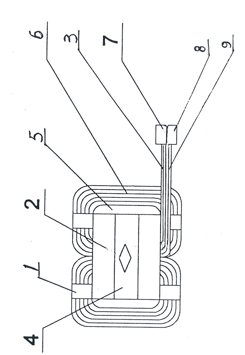
[0019] Refer to attached figure 1 , The new energy storage inductor includes a magnetic core 2, a wire package 6, an insulating sleeve 5, an insulating gasket, a lead wire 3, a terminal 7, a fixing clip 4 and insulating varnish. Two wire packs 6 are set on the magnetic core 2, an insulating sleeve 5 is installed between the magnetic core 2 and the wire pack 6, and an insulating gasket is installed between the magnetic cores, and a fixed clip 4 is used to fix the magnetic core. core, two wire packs are welded with an electric soldering iron at the incoming wire end respectively, and have an incoming wire end lead-out line 3, and an incoming wire terminal 7 is installed at the lead-out wire port, and an electric soldering iron is used to weld the outgoing wire end of the two wire packs respectively with an outgoing wire end lead-out Line 9 is equipped with outlet terminal 8 at the lead-out port, and wire package 6, magnetic core 2 and insulating cover 5 are all dipped in insulat...


PUM


Abstract

The invention provides a new energy storage inductor and a manufacturing method thereof and relates to an energy-storing inductor matched with a new energy inverter and a manufacturing method thereof, which are used for performing energy storage on alternating current / direct current generated by solar energy and wind energy through the new energy storage inductor. The new energy storage inductor comprises magnetic cores, coils, insulating sleeves, an insulation spacer, a lead-out wire, a wiring terminal, fixing clamps and insulated paint, wherein two coils are sleeved on the magnetic cores; each insulating sleeve is arranged between each magnetic core and each coil; the insulation spacer is arranged between the magnetic cores; the magnetic cores are fixed by the fixing clamps; and the coils, the magnetic cores and the insulating sleeves are soaked with the insulated paint. The manufacturing method comprises the following steps of: (1) winding the coils; (2) sleeving the two insulating sleeves on wrapping posts on the two sides of one U-shaped iron core nanocrystalline magnetic core respectively, and strapping and fixing the external part of two U-shaped iron-based nanocrystalline amorphous magnetic cores through the fixing clamps so as to form an 'O' magnetic core; and (3) soaking the crude product of the dried new energy storage inductor with epoxy insulated paint, dropping the paint and baking to manufacture the finished product of the new energy storage inductor.

Description

technical field [0001] The invention relates to a new energy storage inductance and a manufacturing method thereof, which relate to an energy storage inductance matched with a new energy inverter and a manufacturing method thereof, which are used for energy storage of alternating and direct current generated by solar energy and wind energy through a new energy storage inductance . Background technique [0002] At present, various inductors in various new energy inverters are based on E-type and POT-type ferrite energy storage inductors, which are difficult to achieve high efficiency requirements in inverters. [0003] Due to the country's vigorous development of new energy technology, domestic manufacturers have developed various energy storage inductors based on E-type and POT-type, but due to the low conversion efficiency and the large space occupied, the application range of ferrite energy storage inductors is limited. . Contents of the invention [0004] The purpose ...

Claims


Application Information

Patent Timeline
IPC IPC(8): H01F17/04H01F37/00H01F27/30H01F27/24H01F27/32H01F41/00
Inventor 郭磊惠涌
Owner 惠涌
Features
  • R&D
  • Intellectual Property
  • Life Sciences
  • Materials
  • Tech Scout
  • Unparalleled Data Quality
  • Higher Quality Content
  • 60% Fewer Hallucinations
Learn More