
Split knotter

A split-type, knotter technology, applied in packaging, agricultural machinery and implements, applications, etc., can solve the problems of increasing the strength of parts, high requirements for assembly and machining accuracy, complex structure, etc., to reduce replacement costs, reduce Effects of manufacturing and maintenance costs

Inactive Publication Date: 2011-01-26
CHINA AGRI UNIV
View PDF10 Cites 19 Cited by
  • Summary
  • Abstract
  • Description
  • Claims
  • Application Information

AI Technical Summary

Problems solved by technology

However, these knotters are all integrated knotters with complex structures and high requirements for assembly and processing precision.
In addition, multiple structures are concentrated on one part, which increases the load on the strength of the part, and there is a shortage that the entire part needs to be replaced due to the damage of one structure.

Method used


Image

  • Split knotter
  • Split knotter
  • Split knotter

Examples


Embodiment Construction

[0027] The present invention provides a split knotter, which will be further described below in conjunction with the accompanying drawings and specific embodiments.

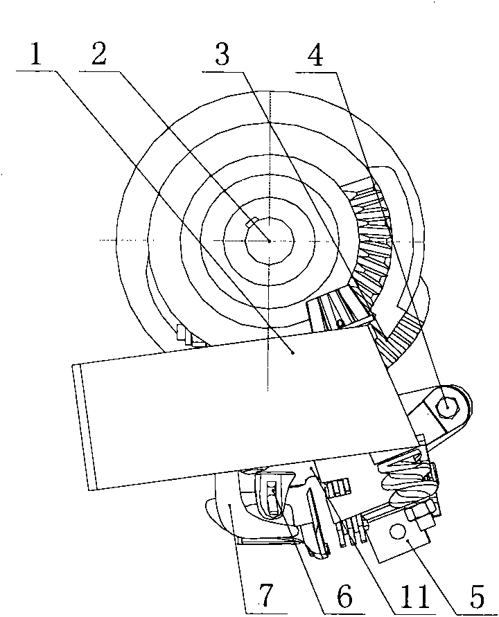
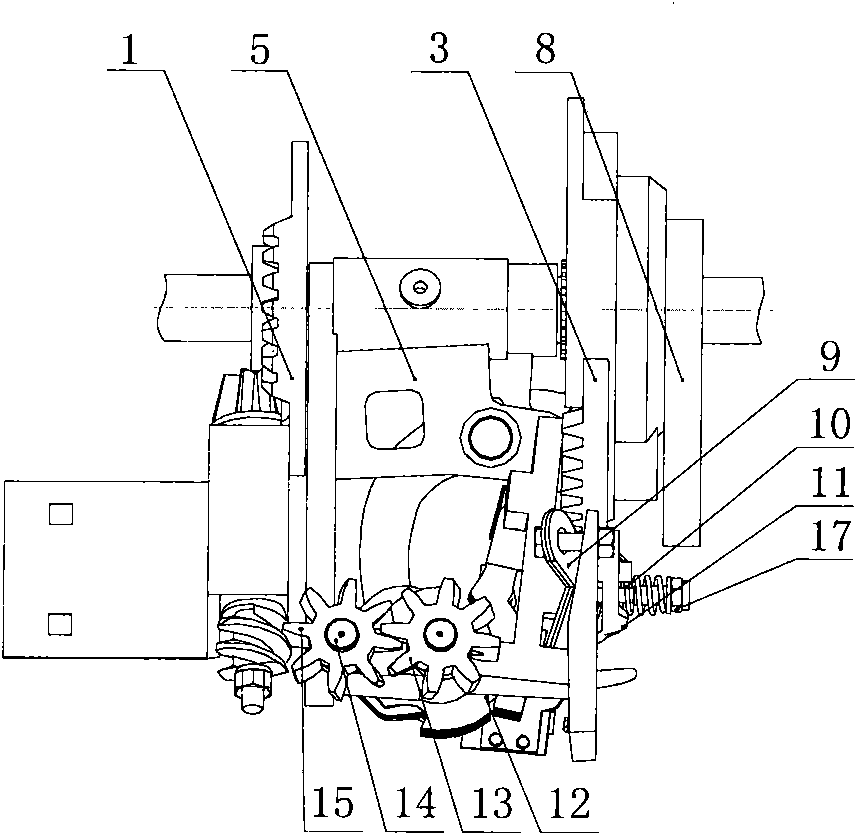
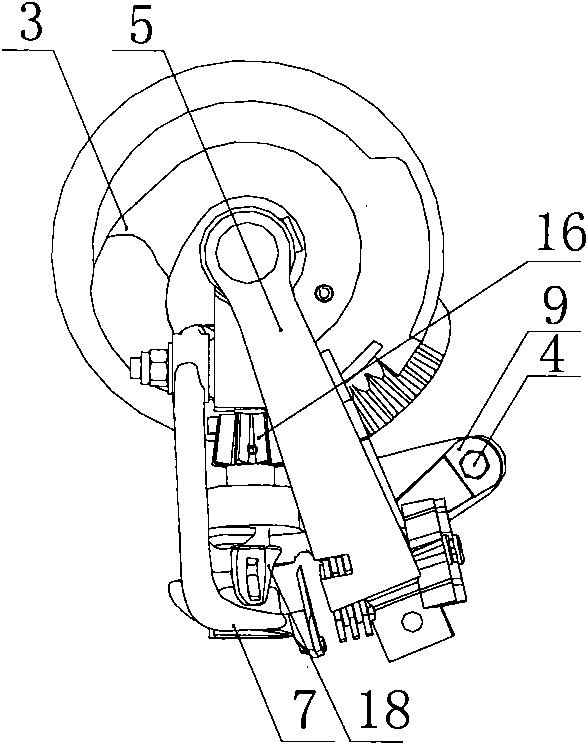
[0028] Figure 1 to Figure 1 0 is the overall assembly diagram, split mechanism diagram and parts diagram of the split knotter of the present invention, respectively. The main body mounting frame 5 of the split knotter mainly includes six shaft holes I, II, III, IV, V, and VI. The shaft hole II intersects with the shaft hole I, and the included angle is 90°-100°. III is perpendicular to shaft hole I, shaft hole IV, shaft hole V, and shaft hole VI are parallel to each other, and the intersection angle between shaft hole V and shaft hole II is less than 90°. The drive shaft 2 is installed in the shaft hole 1 of the main body mounting frame 5, the rope clamp drive mechanism 1 and the split drive disc mechanism 3 are coaxially installed at the two ends of the drive shaft 2, and the clamp rope drive mechanism 1 and t...


PUM


Abstract

The invention relates to a split knotter which belongs to the field of agricultural mechanical equipment. A drive shaft is installed in a shaft hole I of a main installation frame; a rope clamping drive mechanism and a split drive disk mechanism are coaxially installed at both ends of the drive shaft; a cam swinging rod is installed on a shaft hole III of the main installation frame, and the cam swinging rod and the split drive disk mechanism form a cam mechanism; the rope clamping mechanism and a rope clamping right helical gear are coaxial and are installed on a shaft hole V of the main installation frame; a rope clamping left helical gear is installed on a shaft hole VI of the main installation frame; an olecranon intermittent gear and an olecranon tongue are axially connected with an olecranon shaft respectively and installed on a shaft hole II of the main installation frame; and the olecranon tongue and the main installation frame form a small cam mechanism. Key mechanisms of the invention are formed by combining split parts, thereby reducing the processing deformation of integrated parts and the manufacture and maintenance cost of a press baler, being beneficial to the adjustment of relative positions during assembly, overcoming the defect of replacing the whole part due to the damage of a structure, prolonging the service life of the knotter and enhancing the processing strength of the parts.

Description

technical field [0001] The invention relates to a mechanical split soft rope knotter applied to a square grass baler, belonging to the field of agricultural machinery. Background technique [0002] Straw can be used as feed, energy, raw material, fertilizer, etc. It is one of the green renewable energy sources with the greatest potential for development and utilization in new energy sources. In addition to returning the straw directly to the field for use as fertilizer, other uses need to be bundled and transported away. The straw bales produced by domestic round bale balers have irregular shapes, unstable dimensions, and a high rate of loose bales, and round bales take up a lot of space and cost a lot during transportation, especially in long-distance transportation. A square bale baler is used. The knotter is the core component of the square grass baler, which is mainly used to tie the ropes used to fix the compressed straw to prevent loose baling. [0003] At present, ...

Claims


Application Information

Patent Timeline
IPC IPC(8): A01F15/14A01D59/04
Inventor 李洪文李慧王庆杰何进蔡国华孙浩苏艳波卢彩云张学敏李问盈
Owner CHINA AGRI UNIV
Learn More