High-efficiency energy-saving forklift hoisting mechanism

An energy-saving, forklift technology, applied in the direction of lifting devices, etc., can solve the problems of high operating noise, low transmission efficiency, and low service life, and achieve the effects of low operating noise, convenient system installation and long service life.

Active Publication Date: 2011-01-26
SHANXI GUOLI INFORMATION TECH
View PDF6 Cites 5 Cited by
  • Summary
  • Abstract
  • Description
  • Claims
  • Application Information

AI Technical Summary

Problems solved by technology

[0007] The purpose of the present invention is to provide a high-efficiency and energy-saving forklift lifting mechanism to solve the problems of inconvenient installation, low transmission efficiency, low service life, high operating noise and low reliability caused by the hydraulic drive system of the existing battery forklift. technical issues

Method used


Image

  • High-efficiency energy-saving forklift hoisting mechanism
  • High-efficiency energy-saving forklift hoisting mechanism
  • High-efficiency energy-saving forklift hoisting mechanism

Examples


Embodiment 1

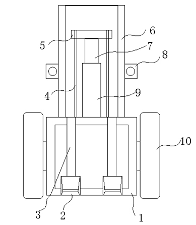
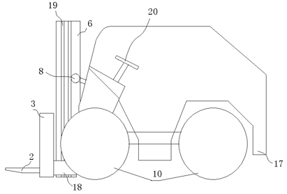
[0025] Such as figure 1 , figure 2 As shown, a high-efficiency and energy-saving forklift lifting mechanism, it at least includes a forklift body 17, a fork frame 1 connected to the front end of the forklift body 17, a fork 2 and a guide frame 6, the fork frame 1 and the guide frame 6 pass through the guide groove 19 sliding connection, the two horizontal forks 2 on the left and the right are slidingly connected to the fork frame 1 through the fork rod 3, the upper end of the guide frame 6 is connected to the upper end of the forklift body 17 through the left and right front big arm drive cylinders 8, and the guide frame 6. The lower end is fixed to the chassis of the forklift body 17. Fork head frame 1 has a fork head guide frame 18 at both ends. Driven by the transmission belt / chain 4, the fork head guide frame 18 slides and moves up and down along the guide frame 6 in the guide groove 19. The two transmission belts One end of the chain 4 is fixed to the fork head frame 1,...

Embodiment 2

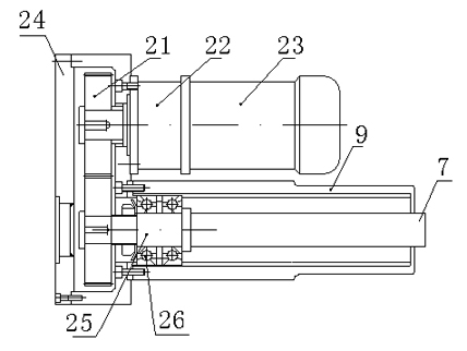
[0028] Such as image 3 As shown, in order to enhance the driving force and balance of the forklift, the electric cylinders 9 in the guide frame 6 are two groups, vertically erected between the left and right frames of the guide frame 6, the left electric cylinder 13 and the right electric cylinder 14 of the two groups of electric cylinders Balanced arrangement, one end of the left drive belt / chain 11 and right drive belt / chain 12 is fixed to the fork frame 1, the other end is fixed on the forklift body 17, there is a forklift moving wheel 10 under the forklift body 17, and the middle of the two drive belts / chains 4 passes through the horizontal The elevating rod 5 is transitionably connected, and the left push rod 15 and the right push rod 16 of the left electric cylinder 13 and the right electric cylinder 14 are vertically connected with the horizontal elevating rod 5 .

[0029] Both groups of electric cylinders include motor 23, gear pair 21, gearbox 24, transmission shaft ...


PUM


Abstract

The invention relates to a battery forklift, in particular to a high-efficiency energy-saving forklift hoisting mechanism. The mechanism at least comprises a forklift body, a fork frame connected at the front end of the forklift body, forks and a guide frame, wherein the fork frame and the guide frame are in sliding connection through a guide groove; two horizontal forks on the left and right are in sliding connection with the fork frame through fork rods; the upper end of the guide frame is connected to the upper end of the forklift body through a left front boom drive cylinder and a right front boom drive cylinder, and the lower end of the guide frame is fixed on the chassis of the fork body; and the fork frame slides and moves up and down in the guide groove along the guide frame under the driving of a transmission belt/chain. The forklift hoisting mechanism is characterized in that: the lower end of a transverse lift rod is vertically fixedly connected with pull rods of electric cylinders; and the electric cylinders are fixed bilaterally symmetrically to the center of the guide frame. The forklift hoisting mechanism adopts an electric ball screw to replace a fork drive cylinder, a rotating cylinder of the booms, a steering cylinder, a fork transverse moving cylinder and other hydraulic cylinders of the battery forklift.

Description

technical field [0001] The invention relates to a battery forklift, in particular to a high-efficiency and energy-saving lifting mechanism for a forklift, which uses an electric ball screw to replace the fork drive cylinder, the front arm rotation cylinder, the steering cylinder and the fork lateral movement cylinder of the battery forklift Battery forklifts such as hydraulic cylinders. Background technique [0002] The power generation of the current battery forklift is provided by the fork drive cylinder, the front arm rotation cylinder, the steering cylinder, and the fork lateral movement cylinder. When the forklift is working, the motor drives the hydraulic pump to rotate, and then the hydraulic pipeline is connected to each oil cylinder, and the oil circuit is controlled by manual and electric valves. But the existing hydraulic system has the following problems: [0003] 1. The connection of the hydraulic pipeline is complex and prone to oil leakage and the installati...

Claims


Application Information

Patent Timeline
Patent Type & Authority Applications(China)
IPC IPC(8): B66F9/075B66F9/24
Inventor 曾卫东潘亚敏
Owner SHANXI GUOLI INFORMATION TECH
Why Eureka
Try Eureka