
Down-the-hole hammer reverse concentric casing drilling tool

A technology of drilling with pipe and reverse circulation, which is applied to drilling equipment, earthwork drilling, and driving devices for drilling in boreholes. It can solve the problems of reduced drilling efficiency, shortened life of drilling tools, and increased drilling costs. Avoid the erosion of the hole wall and the loss of flushing fluid, prevent the cuttings from getting stuck, and avoid repeated crushing effects

Inactive Publication Date: 2011-01-26
JILIN UNIV +1
View PDF6 Cites 20 Cited by
  • Summary
  • Abstract
  • Description
  • Claims
  • Application Information

AI Technical Summary

Problems solved by technology

The above drilling tool systems all adopt the positive circulation slag discharge method. When the hole diameter is large or the formation is complex, the positive circulation slag discharge is difficult, resulting in a decrease in drilling efficiency, a shortened life of the drill tool and an increase in drilling cost; when drilling in a complex formation, it is necessary When obtaining rock ore samples, it is difficult to obtain the rock samples required for mineral exploration; the structure of the drilling tool is complex and the cost is high, and the valve is easily stuck by cuttings when the drill is lifted, which brings inconvenience to the drill
CN1651711A discloses a down-the-hole hammer reverse circulation follow pipe drill bit, which uses two valve structures to change the drilling diameter and realize reverse circulation concentric follow pipe drilling, but the drill bit structure is complicated and the processing cost is high

Method used


Image

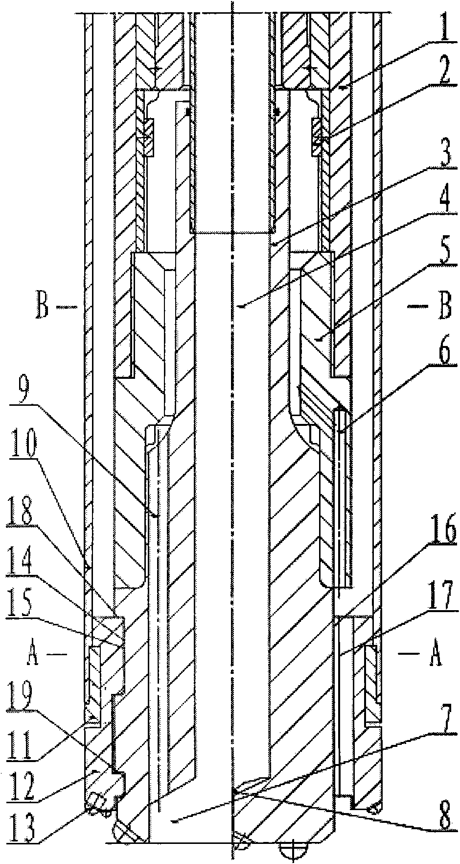
  • Down-the-hole hammer reverse concentric casing drilling tool
  • Down-the-hole hammer reverse concentric casing drilling tool
  • Down-the-hole hammer reverse concentric casing drilling tool

Examples


Embodiment Construction

[0021] Below in conjunction with accompanying drawing and embodiment do further detailed description:

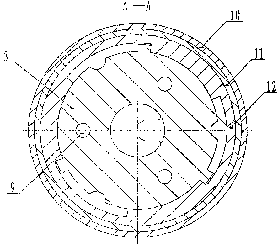
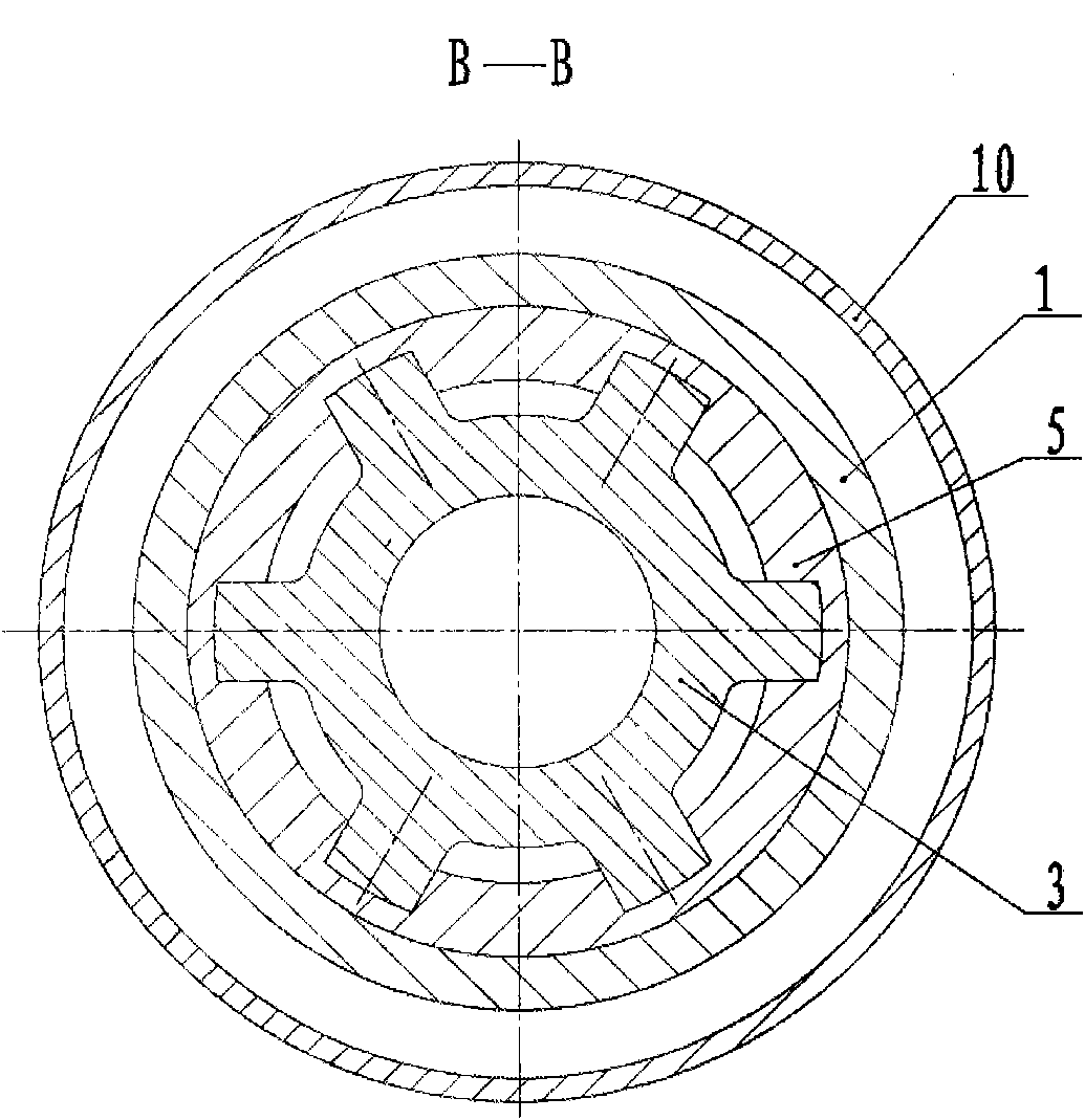
[0022] The DTH hammer reverse circulation concentric heel pipe drilling tool is connected with the guide bit 3 by the hollow DTH hammer 1 through the semicircle clamp 2 and the spline sleeve 5, and the guide bit 3 is provided with an external spline 16 in the axial direction. And cooperate with the inner spline 17 of the annular casing drill bit 12, the guide drill bit 3 is provided with a torsion transmission groove 14, the lower section of the guide drill bit 3 is provided with a bottom spray hole 9, and the lower end of the spline sleeve 5 is provided with an ejector Nozzle 6, diffuser groove 7 is provided at the bottom of central slag discharge channel 4, anti-blocking boss 8 is provided at the bottom of pilot drill bit 3, annular casing drill bit 12 is suspended on the lower end of casing 10 through boot 11, The drill bit alloy 13 is inlaid on the bottom surface of the ...


PUM


Abstract

The invention relates to a down-the-hole (DTH) hammer reverse concentric casing drilling tool. A hollow DTH hammer is connected to a guiding drill through a semicircular block and a spline housing, wherein an outer spline which is arranged on the axial direction of the guiding drill is matched with an inner spline of an annular sleeve drill; the guiding drill 3 is designed as a reverse structure;and an annular casing drill is hung on the lower end of the sleeve through a pipe boot. Compared with the prior art, the guiding drill crashes rock in advance and transmits an impact load to the annular casing drill and drives the drill to rotate, in order to realize simultaneously performing three processes of concentrically crashing, wall protection through the casing and reverse slagging. The double air piping can simultaneously cool the spherical gear alloy of the inner and outer drills and prolong the service life of the drill. Reverse slagging can efficiently clean the hole bottom rock debris, avoid repeated crashing and prevent the drill from being blocked by the rock debris. After ending the casing drilling, the reverse drilling can be performed without exchanging the drill. The casing drill tool has simple structure, low processing cost, long service life and high drilling efficiency.

Description

Technical field: [0001] The invention relates to a rock and soil drilling machine tool for drilling in complex formations, in particular to a down-the-hole hammer for reverse circulation and pipe drilling. Background technique: [0002] The down-the-hole hammer and pipe drilling technology is an efficient drilling method for drilling holes in complex formations such as broken, lost, pebbles, lost and collapsed. It uses the down-the-hole hammer to efficiently break rocks, and uses synchronous follow-up casing to protect the hole wall, so that the three processes of drilling, wall protection and slag discharge can be carried out simultaneously. Existing tubular drilling tools are mainly divided into two categories: eccentric tubular drilling tools and concentric tubular drilling tools. Practice has proved that the existing down-the-hole hammer eccentric heel pipe drilling tools have certain defects, such as: large torque required for drilling, poor concentricity of the drilli...

Claims


Application Information

Patent Timeline
IPC IPC(8): E21B4/06
Inventor 博坤井石滚高建敏王春毅王茂森刘军谢九敬孔海涛何亚清庄志明
Owner JILIN UNIV
Learn More