Energy storage heat pump air conditioner

A heat pump air conditioner and energy storage device technology, which is applied in air conditioning systems, household heating, heating methods, etc., can solve the problem of inability to use peak and valley electricity, and achieve the effects of saving electricity costs, reducing operating time, and reducing operating electricity costs.

Inactive Publication Date: 2012-07-04
法凯涞玛冷暖设备(杭州)有限公司
View PDF2 Cites 0 Cited by
  • Summary
  • Abstract
  • Description
  • Claims
  • Application Information

AI Technical Summary

Problems solved by technology

[0010] The purpose of the present invention is to solve the problem that current mainstream heat pumps cannot use peak and valley electricity, reduce the running time of the main engine when the electricity price is high during the day, and the defects in the above-mentioned characteristics, and provide an energy storage heat pump air conditioner, which can store heat by using an energy storage unit and the characteristics of coldness, the characteristics that substances need to absorb or release heat when they are transformed between two phases, that is, the energy storage unit needs to absorb heat when it melts from a solid state to a liquid state, which is the process of storing heat energy; while the energy storage unit condenses from a liquid state to a liquid state. When the solid state needs to release heat, this is the process of storing cold energy (or releasing heat energy); the energy storage heat pump absorbs heat from the atmospheric environment when the ambient temperature is high, and stores the heat energy until the ambient temperature is low. , and then released as the heat source of the heat pump host after being upgraded to meet the needs of production or life and achieve the purpose of heating

Method used


Image

  • Energy storage heat pump air conditioner
  • Energy storage heat pump air conditioner
  • Energy storage heat pump air conditioner

Examples


Embodiment Construction

[0022] The technical solutions of the present invention will be further specifically described below through the embodiments and in conjunction with the accompanying drawings.

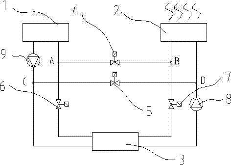
[0023] Such as figure 1 As shown, in this embodiment, an energy storage heat pump air conditioner is provided with an energy storage device 1, a cold and heat source tower 2 and a heat pump host 3, and two pipelines are arranged between the energy storage device 1 and the heat pump host 3, one of which is A first pump 9 is provided on the pipeline, and a first shut-off valve 6 is provided on the second pipeline; two pipelines are also provided between the cold heat source tower 2 and the heat pump host 3, one of which is provided with a The second pump 8 is provided with a second shut-off valve 7 on the other pipeline.

[0024] A first port A is set between the energy storage device 1 and the first shut-off valve 6, a second port B is set between the cold heat source tower 2 and the second shut-off va...


PUM


Abstract

The invention relates to a heat energy conversion and utilization technology, in particular to an energy storage heat pump air conditioner which can solve the problems that an existing mainstream heat pump can not utilize peak-valley electricity and reduce the running time of a host during peak electricity at night, the energy storage heat pump air conditioner comprises an energy storage device, a cold and heat source tower and a heat pump host, two pipelines are arranged between the energy storage device and the heat pump post, a first pump is arranged on one pipeline, and a first shut-off valve is arranged on the second pipeline; two pipelines are arranged between the cold and heat source tower and the heat pump post, a second pump is arranged on one pipeline, and a second shut-off valve is arranged on the other pipeline; a first interface is arranged between the energy storage device and the first shut-off valve, a second interface is arranged between the cold and heat source towerand the second shut-off valve, and a third shut-off valve is arranged between the first interface and the second interface; and a third interface is arranged between the heat pump host and the first pump, a fourth interface is arranged between the cold and heat source tower and the second pump, the third interface and the fourth interface are connected by using the pipeline, and a fourth shut-offvalve is arranged between the third interface and the fourth interface. The energy storage heat pump air conditioner can reasonably utilize the peak-valley electricity and reduce the running power fare.

Description

technical field [0001] The invention relates to the technical field of thermal energy conversion and utilization, in particular to an energy storage heat pump air conditioning system for cooling and heating. Background technique [0002] When the heat pump is heating, the heat source is generally the local air, the geothermal heat of the earth, the heat of underground or surface water, the residual waste heat in the production or living process, etc. Among them, the geothermal heat of the earth and the residual waste heat in the production or living process are the most important. Constant, but other heat sources change with time, especially when the air source is used as the heat source of the heat pump, the heating effect of the heat pump is greatly affected by time. [0003] For 24 hours a day, the temperature and humidity of the air will vary with time. During the day, due to direct sunlight, the air temperature and surface temperature are relatively high. At night, ther...

Claims


Application Information

Patent Timeline
Patent Type & Authority Patents(China)
IPC IPC(8): F24F5/00
Inventor 李进华陈建平
Owner 法凯涞玛冷暖设备(杭州)有限公司
Why Eureka
Try Eureka