
Display panel

A display panel and display medium layer technology, which is applied in nonlinear optics, instruments, optics, etc., can solve the problems of difficult design of narrow frame of liquid crystal display panel and limited position of frame glue setting, etc.

Inactive Publication Date: 2011-01-26
AU OPTRONICS CORP
View PDF4 Cites 36 Cited by
  • Summary
  • Abstract
  • Description
  • Claims
  • Application Information

AI Technical Summary

Problems solved by technology

[0003] However, since many wires or driving circuits are arranged in the peripheral area of ​​the existing liquid crystal display panel, there are many restrictions on the placement of the sealant for bonding the array substrate and the color filter substrate, especially in the current When the frame glue uses conductive frame glue, the setting position of the frame glue is more limited, which also causes difficulties in the narrow frame design of the LCD panel

Method used


Image

  • Display panel
  • Display panel
  • Display panel

Examples


Embodiment Construction

[0059] In order for those skilled in the art to have a better understanding of the present invention, preferred embodiments of the present invention are enumerated below, together with the accompanying drawings, to describe in detail the composition and desired effects of the present invention.

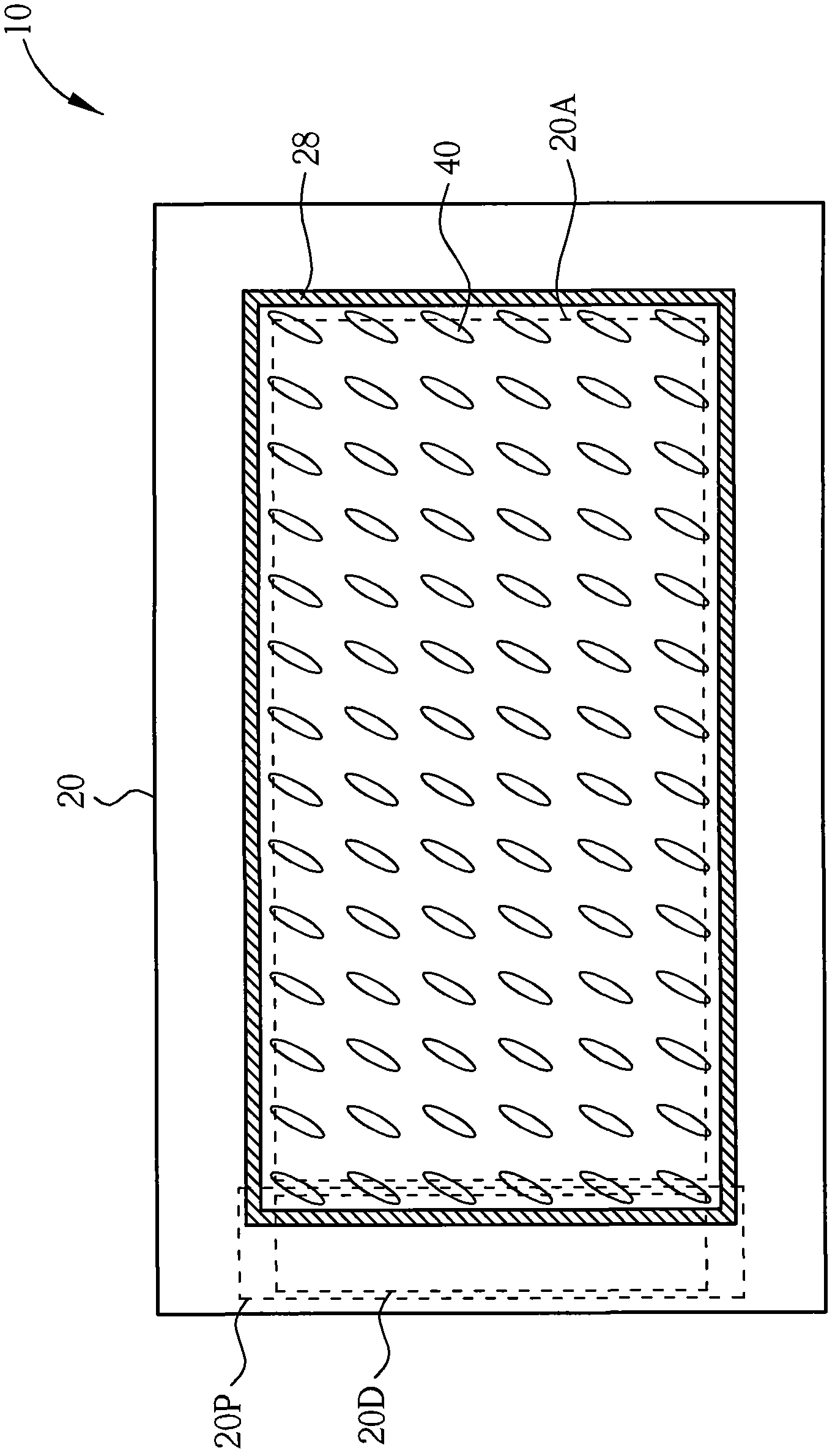
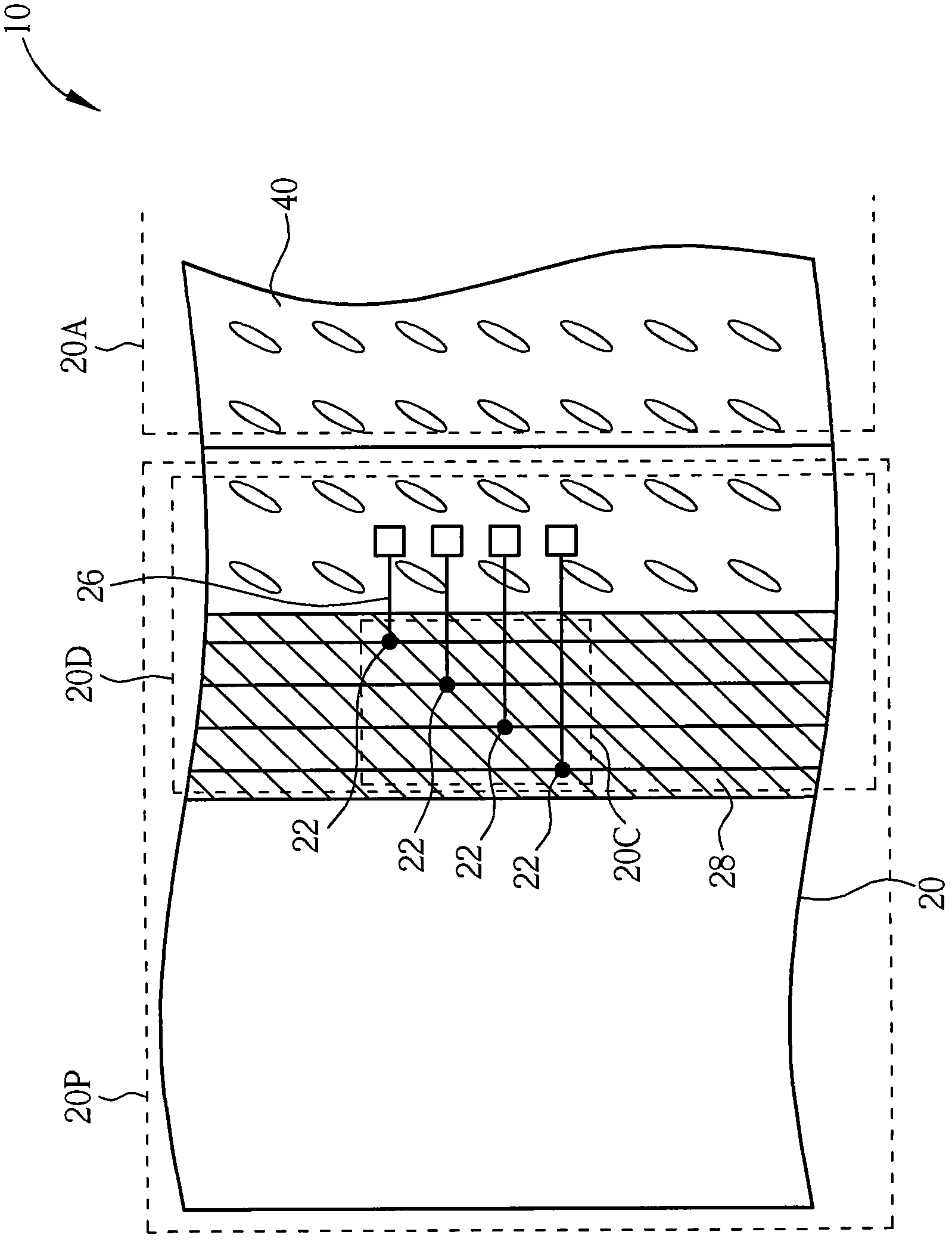
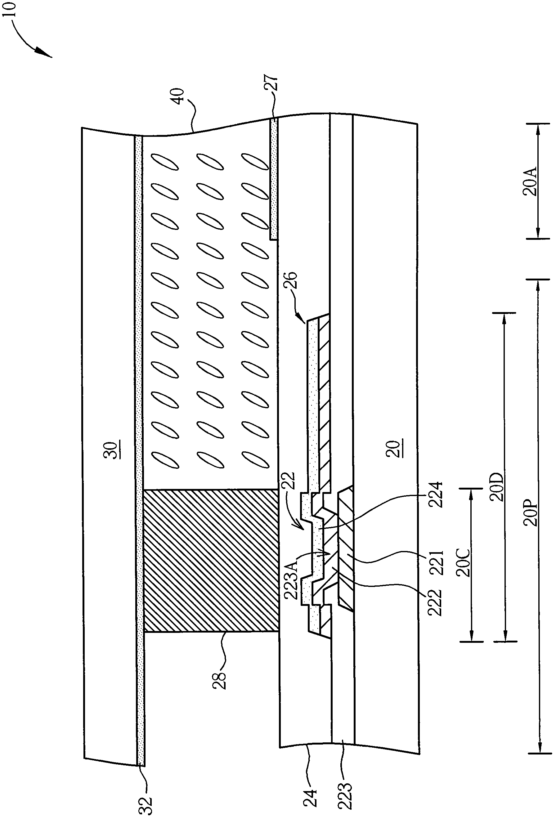
[0060] Please refer to Figure 1 to Figure 3 . Figure 1 to Figure 3 It is a schematic diagram of a display panel according to a first preferred embodiment of the present invention, wherein figure 1 shows the top view of the display panel, figure 2 A partial schematic diagram of the display panel is shown, and image 3A schematic cross-sectional view of the display panel is shown. In this embodiment, the display panel 10 is a liquid crystal display panel, but not limited thereto, and in order to clearly show the characteristics of the display panel of this embodiment, figure 1 and figure 2 Some elements such as the second substrate and the display medium layer are not shown. S...


PUM


Abstract

The invention relates to a display panel comprising a first base panel, a second base panel, a display medium layer, a signal transfer structure, a protecting layer and frame glue, wherein the first base panel comprises a driving zone and a peripheral zone, the peripheral zone comprises a driving circuit zone which comprises a signal transfer zone; the second base panel and the first base panel are oppositely arranged; the display medium layer is arranged between the first base panel and the second base panel; the signal transfer structure is arranged in the signal transfer zone of the first base panel; the protecting layer is arranged on the first base panel and at least completely coats the signal transfer structure; and the frame glue is arranged on the protecting layer of the peripheral zone and used for splicing the first base panel and the second base panel. As the protecting layer of the display panel in the invention completely coats the signal transfer structure and can further completely cover a driving circuit, the position of the frame glue is not limited by the signal transfer structure and the driving circuit and can be arbitrarily changed in the peripheral zone of the first base panel as required, and the area of the peripheral zone can be effectively reduced so that the design of a narrow frame is realized.

Description

technical field [0001] The invention relates to a display panel, in particular to a display panel in which a signal transfer structure in a drive circuit area is completely covered by a protective layer. Background technique [0002] Liquid crystal display panels have been widely used in products such as flat-screen TVs, notebook computers, and personal digital assistants due to their thin and light appearance, low power consumption, and no radiation pollution, and have replaced traditional cathode ray (Cathode Ray Tube, CRT) monitors have become mainstream products on the market. [0003] However, since many wires or driving circuits are arranged in the peripheral area of ​​the existing liquid crystal display panel, there are many restrictions on the placement of the sealant for bonding the array substrate and the color filter substrate, especially in the current When the frame glue uses a conductive frame glue, the setting position of the frame glue is more limited, which...

Claims


Application Information

Patent Timeline
Patent Type & Authority Applications(China)
IPC IPC(8): G02F1/1339G02F1/1333G02F1/13
Inventor 黄俊豪彭中宏
Owner AU OPTRONICS CORP
Learn More