Supercharge Your Innovation With Domain-Expert AI Agents!

Method and device for transmitting radio link failure information

A wireless link failure and identification information technology, applied in the handover field of user terminals, can solve the problems of reducing self-optimization of handover parameters, inaccurate handover parameter optimization, and wrongly sending RLF information to the target base station, so as to achieve simple and practical implementation Effect

Active Publication Date: 2015-07-22
盐城市西方科技有限公司
View PDF4 Cites 0 Cited by
  • Summary
  • Abstract
  • Description
  • Claims
  • Application Information

AI Technical Summary

Problems solved by technology

[0010] In the judgment method of the above-mentioned handover scenario, eNB A determines the cell and the base station in which RLF occurs for the UE according to the PCI information in the RRC re-establishment request message of the UE. If there is PCI confusion of the cell, that is, the PCI of the two cells is the same , then eNB A may identify the wrong cell where RLF occurs and select the wrong target base station for sending RLF information when sending RLF information, that is, the PCI information in the RRC re-establishment request message cannot uniquely identify the cell where RLF occurs Cell b and base station eNB B, resulting in inaccurate handover parameter optimization, reducing the function of handover parameter self-optimization

Method used


Image

  • Method and device for transmitting radio link failure information
  • Method and device for transmitting radio link failure information
  • Method and device for transmitting radio link failure information

Examples


Embodiment 1

[0043] Figure 4 It is a flow chart of Embodiment 1 of the method for sending wireless link failure information in the present invention, as shown in Figure 4 As shown, the method for sending wireless link failure information in this example includes the following steps:

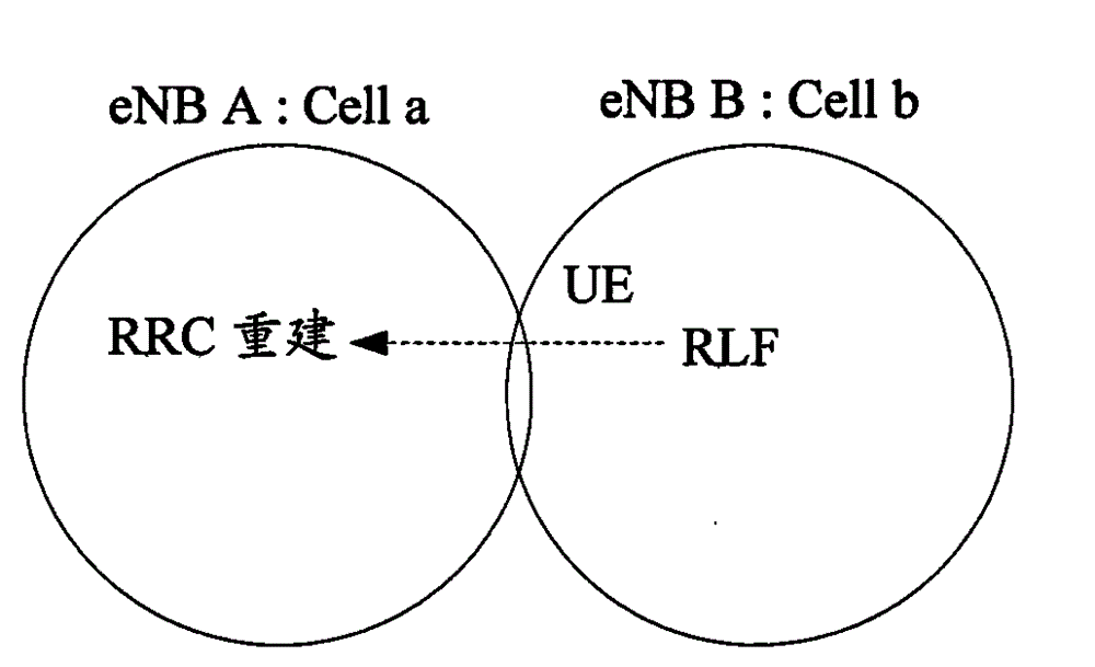
[0044] Step 401: UE is in connected state in cell b managed by eNB B, and radio link failure RLF occurs in cell b due to RRC reconfiguration failure, handover failure or other reasons.

[0045] Step 402: After the radio link failure RLF occurs in the cell Cell b, the UE selects the cell Cell a under the jurisdiction of the eNB A to perform RRC re-establishment through the cell selection process, and the UE sends an RRC re-establishment request message to the eNB A. The RRC re-establishment request message contains ECGI information of the RLF-occurring cell Cell b.

[0046] Step 403: After receiving the RRC re-establishment request message from the UE, eNB A finds the target base station eNB B to which Cel...

Embodiment 2

[0051] Figure 5 It is a flow chart of Embodiment 2 of the method for sending wireless link failure information in the present invention, as shown in Figure 5 As shown, the method for sending wireless link failure information in this example includes the following steps:

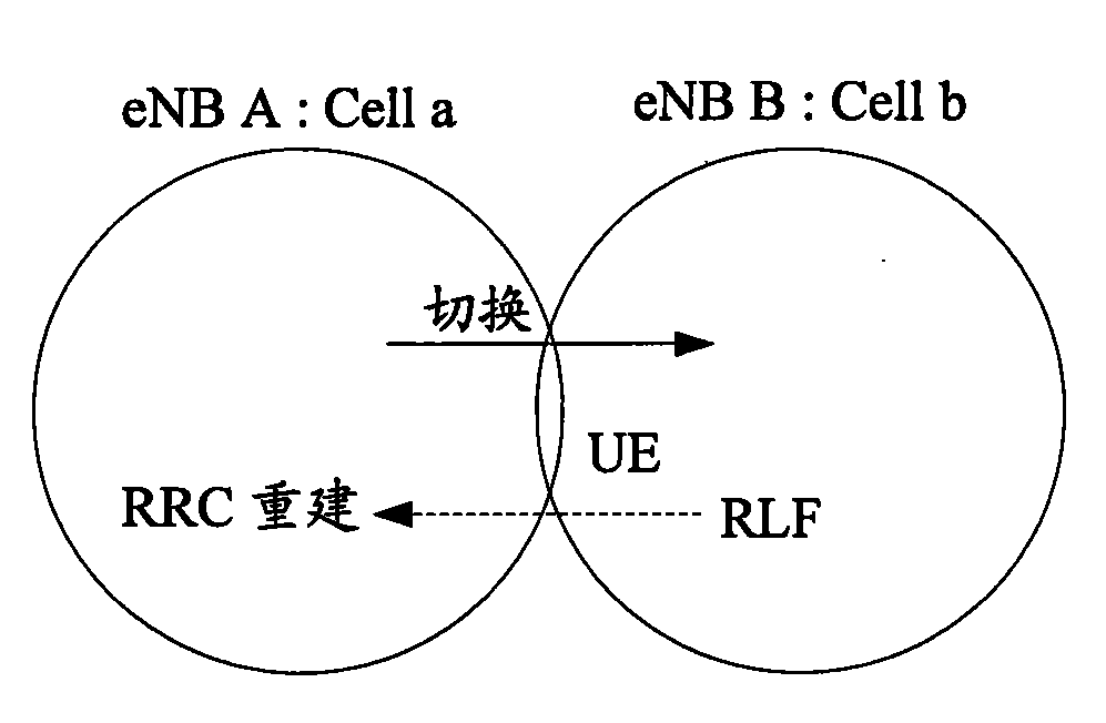
[0052] Step 501: UE is in connected state in cell b managed by eNB B, and radio link failure RLF occurs in cell b due to RRC reconfiguration failure, handover failure or other reasons.

[0053] Step 502: After a radio link failure RLF occurs in the cell Cell b, the UE selects the cell Cell a under the jurisdiction of the eNB A to perform RRC re-establishment through the cell selection process, and the UE sends an RRC re-establishment request message to the eNB A. In the RRC re-establishment request message, in addition to the PCI information of the existing RLF-occurring cell Cell b, it also contains the center frequency point information of the cell Cell b.

[0054] Step 503: After receiving the RRC re-e...


PUM


Abstract

The invention discloses a method for transmitting radio link failure (RLF) information, comprising the following steps: user equipment transmits radio resource control (RRC) rebuilding request information to a target cell when the user equipment has RLF in the cell, wherein the RRC rebuilding request information carries unique identifier information of the cell where RLF happens; after a base station subordinate to the target cell receives the RRC rebuilding request information, when transmitting the RLF information to a base station subordinate to the cell where RLF happens, the base station subordinate to the target cell determines the base station subordinate to the cell where RLF happens via the unique identifier information of the cell where RLF happens, and the RLF information includes the unique identifier information of the cell where RLF happens. The invention simultaneously discloses a device of the method. The invention can accurately notify the base station of the RLF information via the unique identifier information of the cell where RLF happens, thus making accurate judgment on the scenes subjected to handover failure. The technical scheme is simple to implement and practical.

Description

technical field [0001] The present invention relates to handover technology of a user terminal, in particular to a method and device for sending radio link failure information in a Long Term Evolution (LTE, Long Term Evolution) system. Background technique [0002] The LTE network consists of an Evolved Universal Terrestrial Radio Access Network (E-UTRAN, Evolved Universal Terrestrial Radio AccessNetwork), an evolved base station (eNB, Evolved NodeB) and an evolved packet switching center (EPC, Evolved Packet Core). A collection of eNBs that are connected to the E-UTRAN and the EPC through the S1 interface, and the eNBs can be connected through the X2. S1 and X2 are logical interfaces. One EPC can manage one or more eNBs, one eNB can also be controlled by multiple EPCs, and one eNB can manage one or more cells. [0003] Self Organizing Network (SON, Self Organizing Network) is a technology for automatic network configuration and optimization. The feature of this technolog...

Claims


Application Information

Patent Timeline
Patent Type & Authority Patents(China)
IPC IPC(8): H04W36/00H04W76/02
Inventor 韩立锋和峰
Owner 盐城市西方科技有限公司
Features
  • R&D
  • Intellectual Property
  • Life Sciences
  • Materials
  • Tech Scout
  • Unparalleled Data Quality
  • Higher Quality Content
  • 60% Fewer Hallucinations
Learn More