LED lighting control device
A technology of LED lighting and control devices, applied in lighting devices, energy-saving control technology, lamp circuit layout, etc., can solve the problems of lack of intelligence, poor dimming flexibility, LED output brightness adjustment, etc., to improve comfort and increase power The effect of improving conversion efficiency and using efficiency
- Summary
- Abstract
- Description
- Claims
- Application Information
AI Technical Summary
Problems solved by technology
Method used
Image

Examples
Embodiment Construction
[0017] The present invention will be described in further detail below in conjunction with the accompanying drawings and embodiments. It should be understood that the specific examples described here are only used to explain the present invention, not to limit the present invention.
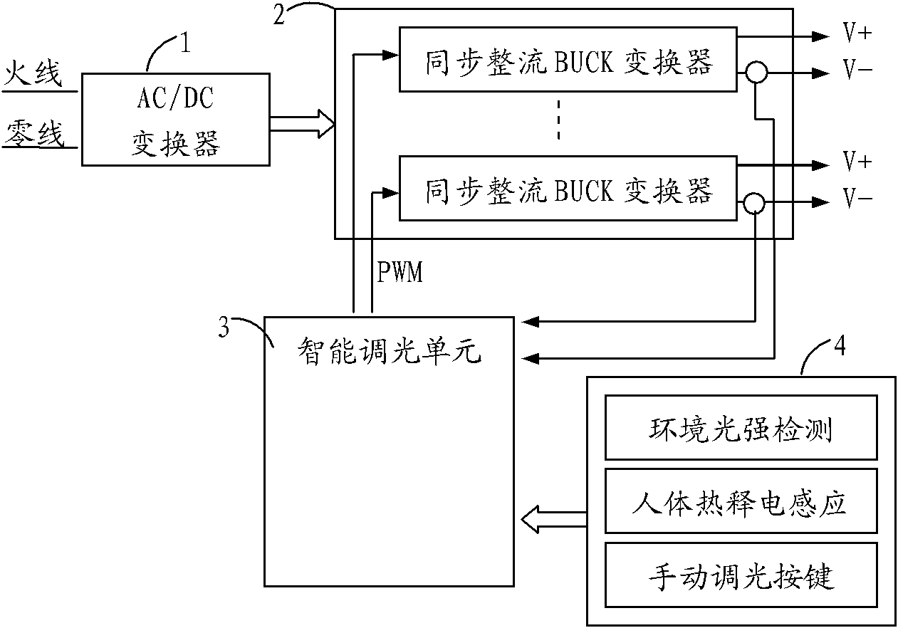
[0018] refer to figure 1 , the present invention includes an AC / DC conversion module 1 connected to an external power supply, a constant current drive module 2, an intelligent dimming unit 3 and an environmental information collection unit 4.
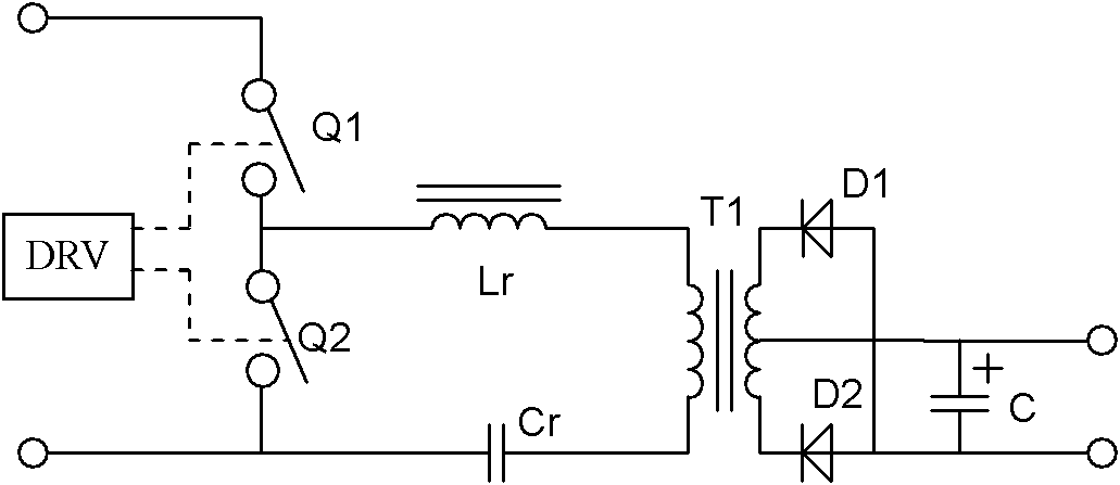
[0019] The AC / DC conversion module 1 converts the mains power into a constant-voltage DC power supply, and implements various circuits, such as a flyback conversion circuit and a forward conversion circuit, but its power conversion efficiency is low. The key reason is that there are defects in the circuit topology. The preferred LLC half-bridge resonant conversion circuit of the present invention realizes constant voltage output, such as image 3 As show...
PUM
 Abstract
Description
Claims
Application Information
 - R&D
- Intellectual Property
- Life Sciences
- Materials
- Tech Scout
- Unparalleled Data Quality
- Higher Quality Content
- 60% Fewer Hallucinations
Browse by: Latest US Patents, China's latest patents, Technical Efficacy Thesaurus, Application Domain, Technology Topic, Popular Technical Reports.
© 2025 PatSnap. All rights reserved.Legal|Privacy policy|Modern Slavery Act Transparency Statement|Sitemap|About US| Contact US: help@patsnap.com