
Device for filtering electromagnetic waves

An electromagnetic wave and filter technology, which is applied in the field of electromagnetic wave filter devices, can solve the problems of inability to obtain zero point characteristics, gain deterioration, and difficulty in avoiding interference waves, etc., and achieve the effect of suppressing noise components

Inactive Publication Date: 2011-01-26
PANASONIC CORP
View PDF6 Cites 1 Cited by
  • Summary
  • Abstract
  • Description
  • Claims
  • Application Information

AI Technical Summary

Problems solved by technology

For example, if the beam half width is reduced due to shadowing, the space in which communication can be limited
In addition, by setting the electromagnetic wave filter device, the half-width of the beam is increased unnecessarily, which easily leads to the reception of unnecessary multiplexed interference waves.
Gain degradation due to shadowing also limits the distance that can be communicated
In addition, when installing an electromagnetic wave filter device, there may be a case where the null characteristic cannot be obtained at the radiation angle that should have the null characteristic, so it may be difficult to avoid the influence of the interference wave

Method used


Image

  • Device for filtering electromagnetic waves
  • Device for filtering electromagnetic waves
  • Device for filtering electromagnetic waves

Examples


Embodiment 1

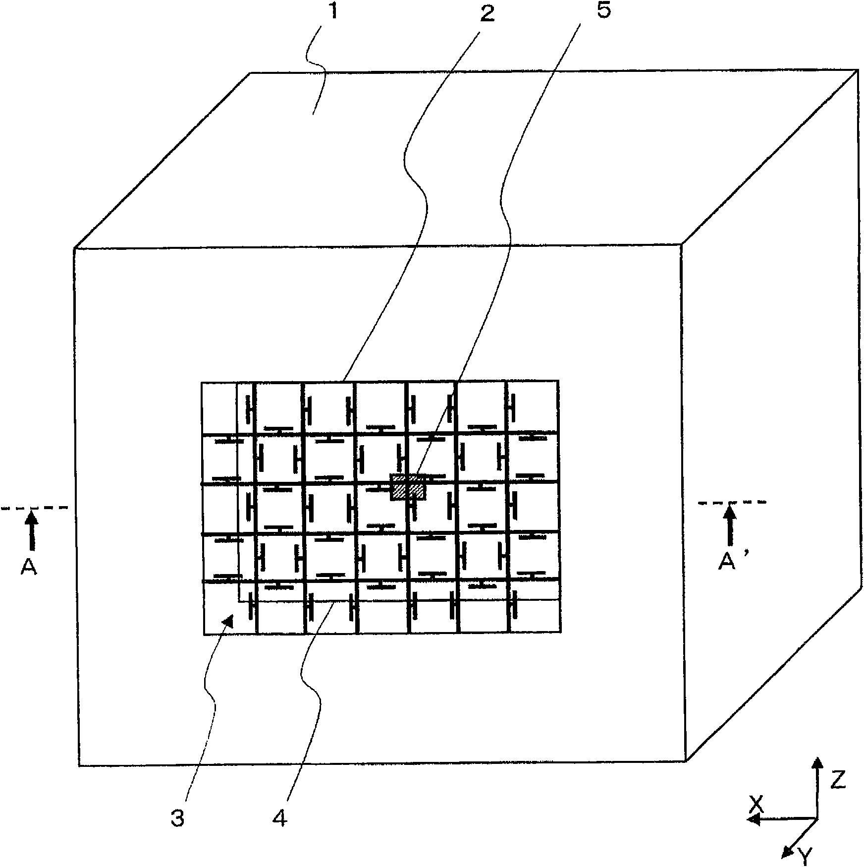
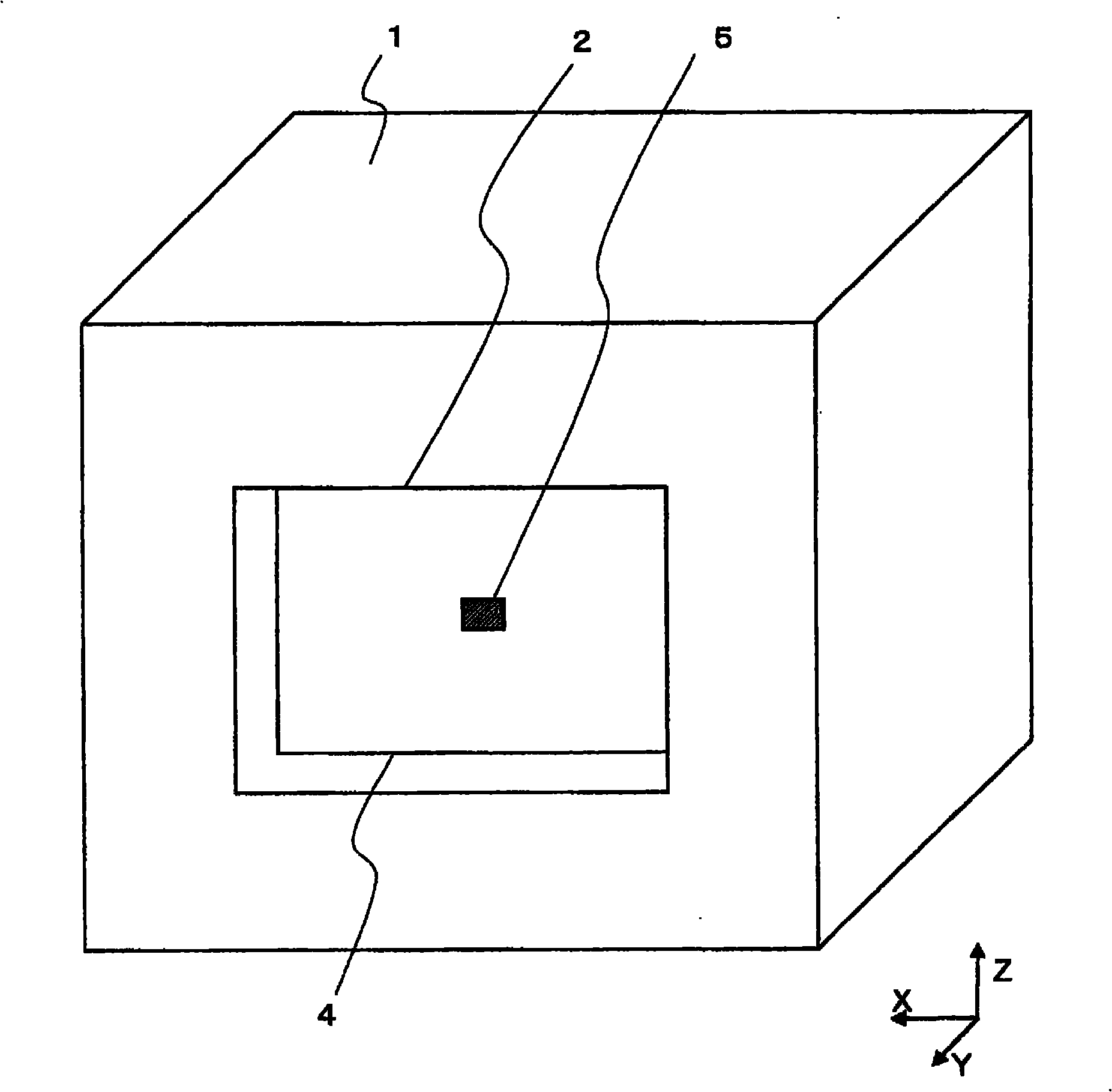
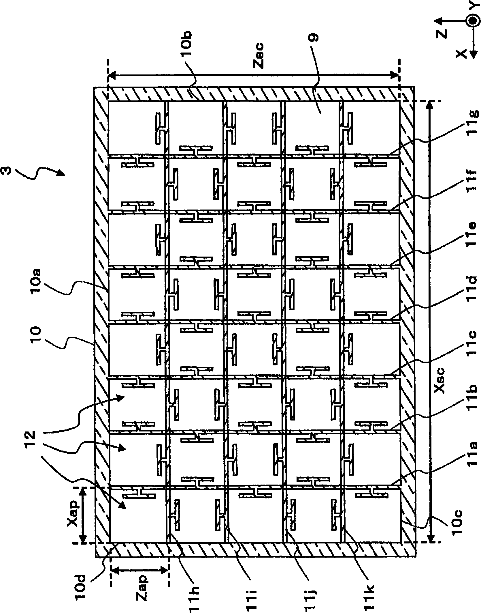
[0103] For actually verifying the beneficial effect of the present invention, made based on Figure 7 The radome of the first embodiment of the electromagnetic wave filter device 3B and based on image 3 Radomes of the second and third embodiments of the electromagnetic wave filter device 3 . In addition, radomes of the first to fifth comparative examples were produced as comparison objects of these examples and typical examples of the prior art. The fabricated examples and comparative examples are the same except for the main parameters of the configuration of the electromagnetic wave filter device. In the following instructions, refer to figure 1 etc. represent the XYZ coordinates.

[0104] A vertically polarized chip antenna formed on an antenna substrate 4 made of aluminum oxide (Alumina) is used as the antenna element 5 accommodated in the shield conductor 1 . The antenna element 5 has dimensions of 0.8 mm×0.95 mm. The resonant frequency is designed to be 60GHz. Und...


PUM


Abstract

A device for filtering electromagnetic waves is provided with: a shield conductor (1); a shield opening (2) provided in the shield conductor (1); a plurality of strip conductors (11), which are connected at the both ends to the shield conductor (1) and divide the shield conductor (1) into a plurality of openings (12); and a plurality of stub conductors (13) arranged on the strip conductors (11) at predetermined intervals, respectively. Each stub conductor (13) passes through electromagnetic waves at a predetermined frequency in the device for filtering electromagnetic waves without substantially affecting radiation of the electromagnetic waves at the predetermined frequency, by preventing a current at a predetermined frequency from flowing in each strip conductor (11) due to the electromagnetic waves which are at the predetermined frequency and passing through the device for filtering electromagnetic waves.

Description

technical field [0001] The present invention relates to an electromagnetic wave filter device which is necessary when an antenna device for transmitting and receiving analog high-frequency signals such as microwave frequency bands and millimeter wave bands or digital signals is mounted on electronic equipment. The present invention is used in an electronic device having a wireless communication function such as moving image transmission, especially in a radome including an electromagnetic wave filter device or a similar electromagnetic wave filter device having the following functions: The radiation pattern of the predetermined frequency used by the wireless communication function does not deteriorate, and the unnecessary radiation of the noise generated inside the electronic device to the external space is suppressed. Background technique [0002] In recent years, wireless technology for moving image transmission has been extensively discussed, and specifications using mill...

Claims


Application Information

Patent Timeline
Patent Type & Authority Applications(China)
IPC IPC(8): H05K9/00G01S7/03H01Q15/12H01Q15/14
CPCH01Q3/46H01Q15/0006H01Q15/0013H05K9/006H01Q15/0053
Inventor 菅野浩
Owner PANASONIC CORP
Learn More