Universal detection device of engine valve lift

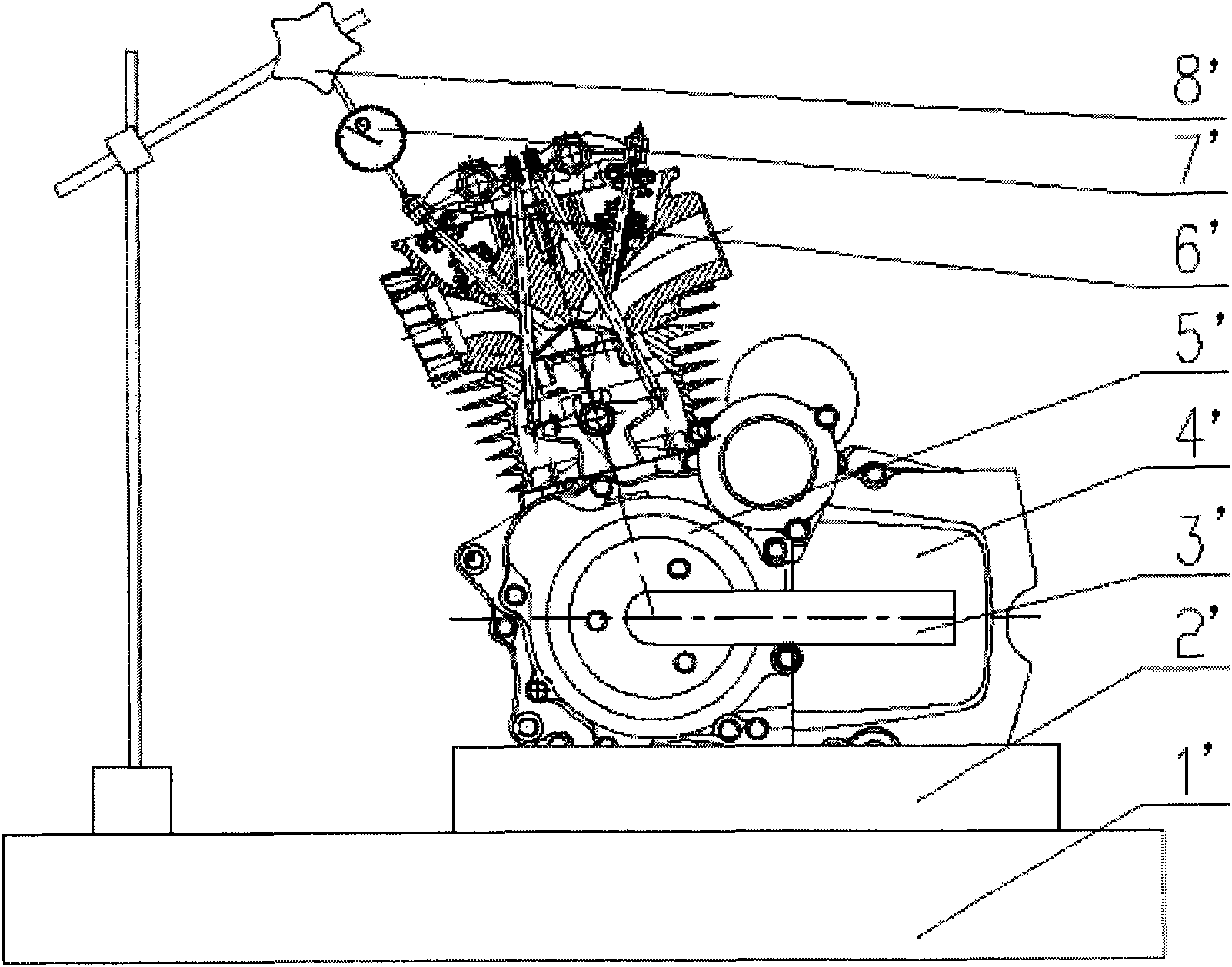
A technology for engine valves and detection devices, which is applied in the direction of mechanical measuring devices, measuring devices, and mechanical devices, etc. It can solve the problems of wooden fixing frame 2' easy to wear, depend on the accuracy of measurement values, and angle system errors, etc., and achieve easy operation , reduce the torque, and ensure the effect of accuracy

Active Publication Date: 2011-02-02
NANJING JINCHENG MACHINERY
View PDF4 Cites 8 Cited by
  • Summary
  • Abstract
  • Description
  • Claims
  • Application Information

AI Technical Summary

Problems solved by technology

[0003] The existing valve lift testing device has the following disadvantages: the existing testing device has a temporary shortcoming; the engine 4' is placed on the wooden fixed frame 2' and the magnetic frame 8' is placed on the workbench 1', and both positioning references It is not the same, and the wooden fixing frame 2' is easy to wear, and the position of the engine 4' will change every time it is measured; The error of the angle system is very large; the accuracy of the measurement value of the existing test device depends on the operator's experience; the wrench 3' rotates the crankshaft angle, and it is difficult to guarantee the accuracy of each degree by stepping one step after another for a long time

Method used


Image

  • Universal detection device of engine valve lift
  • Universal detection device of engine valve lift
  • Universal detection device of engine valve lift

Examples


Embodiment Construction

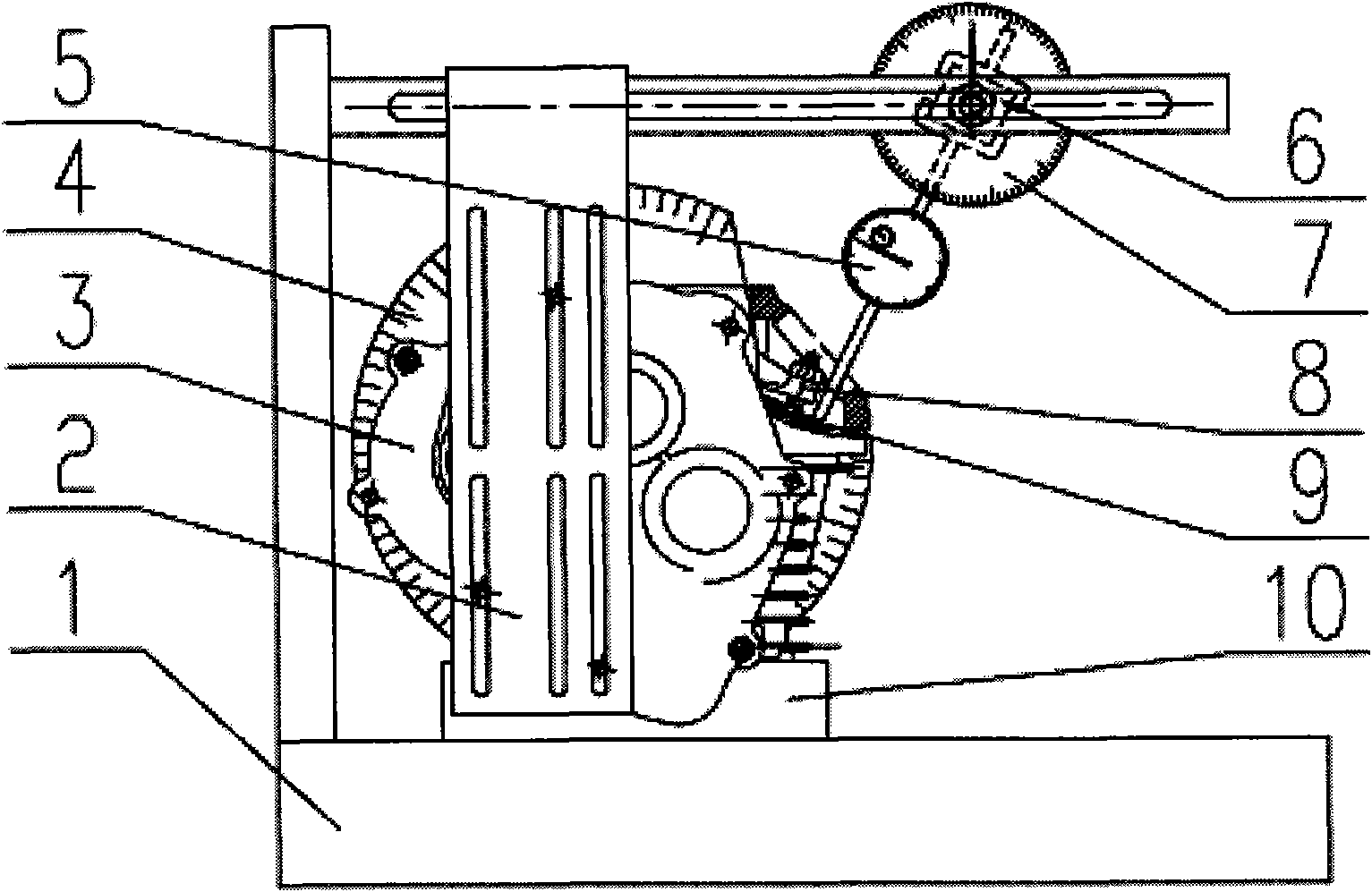
[0017] The embodiments of the present invention are described in detail below. This embodiment is implemented on the premise of the technical solution of the present invention, and detailed implementation methods and specific operating procedures are provided, but the protection scope of the present invention is not limited to the following implementation example.

[0018] Such as figure 2 As shown, this embodiment includes a workbench 1, a connecting plate 2, a deceleration mechanism 3, a first angle dial 4, a dial indicator 5, a connecting rod 6, a second angle dial 7, a valve rocker arm 8, a valve spring seat 9 and Steel fixed frame 10, wherein: the steel fixed frame 10 is fixed on the workbench 1, the steel fixed frame 10 is fixedly connected with the deceleration mechanism 3, the deceleration mechanism 3 is fixedly connected with the connecting plate 2, and the first angle dial 4 is fixed on the deceleration On the output shaft of the mechanism 3, the dial indicator 5 a...


PUM


Abstract

The invention discloses a universal detection device of an engine valve lift, which comprises a dial indicator, a fixed frame, a connecting plate, a speed reducing mechanism, a first angle dial and a second angle dial, wherein the fixed frame is fixedly connected with the speed reducing mechanism, the speed reducing mechanism is fixedly connected with the connecting plate, the first angle dial is arranged on the output shaft of the speed reducing mechanism, and the dial indicator is fixedly connected with the second angle dial. The universal detection device can be used as fixed equipment for long-term use and can ensure the precision since references are relatively fixed; the references of all the parts of the device are unified, the errors are fixed, the precision is within an acceptable range, and a relative error limit can be computed through absolute errors; the axial line of the dial indicator and the axial line of a valve rod are easily adjusted to be collinear, and the valve stroke can be truly reflected through measured numerical values; through the two-stage speed reducing mechanism, the rotating speed of the output shaft can be decreased, the torque of an input shaft is reduced, the operation is quite easy, and particularly a unidirectional clutch prevents the input shaft from reversely rotating and further ensures the rotating accuracy of the input shaft; and the device has strong adaptability.

Description

technical field [0001] The invention relates to a device in the technical field of engine valve detection, in particular to a universal detection device for engine valve lift. Background technique [0002] It is often necessary to detect the lift of the intake and exhaust valves when mapping the cam profile or checking the phase diagram of the intake and exhaust valves of the engine. The existing detection devices have difficulty in positioning, data distortion and large errors. as attached figure 1 As shown, it is the detection device of the existing engine valve lift, the detection device includes a workbench 1', a wooden fixing frame 2', a wrench 3', an engine 4', a magneto rotor 5', a valve rocker arm 6', a thousand The sub-meter 7' and the magnetic frame 8', in which: the engine 4' is horizontally installed in the wooden fixed frame 2', the wooden fixed frame 2' is horizontally installed on the workbench 1', and the dial indicator 7' is set on the magnetic frame 8', ...

Claims


Application Information

Patent Timeline
Patent Type & Authority Applications(China)
IPC IPC(8): G01B5/02
Inventor 支峰
Owner NANJING JINCHENG MACHINERY
Why Eureka
Try Eureka