Tool and method for measuring deflection angle of airplane control surface

A technology for rudder surface deflection and angle measurement, which is applied in the field of testing and machinery, and can solve problems such as inapplicable dynamic measurement, difficult installation, and difficult measurement

Active Publication Date: 2011-02-02
XIAN AIRCRAFT DESIGN INST OF AVIATION IND OF CHINA
View PDF2 Cites 51 Cited by
  • Summary
  • Abstract
  • Description
  • Claims
  • Application Information

AI Technical Summary

Problems solved by technology

[0003] The object of the present invention is: to propose a kind of measuring tool and measuring method of deflection angle of aircraft rudder surface, overcome the existing aircraft rudder surface deflection angle measurement tool is difficult to install, difficult to measure, not suitable for dynamic measurement, or need to dismantle the body or skin It cannot meet the shortcomings of dismantling the fuselage during the on-board test before the first flight.

Method used


Image

  • Tool and method for measuring deflection angle of airplane control surface
  • Tool and method for measuring deflection angle of airplane control surface
  • Tool and method for measuring deflection angle of airplane control surface

Examples


Embodiment Construction

[0033] The present invention will be described in detail below in conjunction with the accompanying drawings and embodiments.

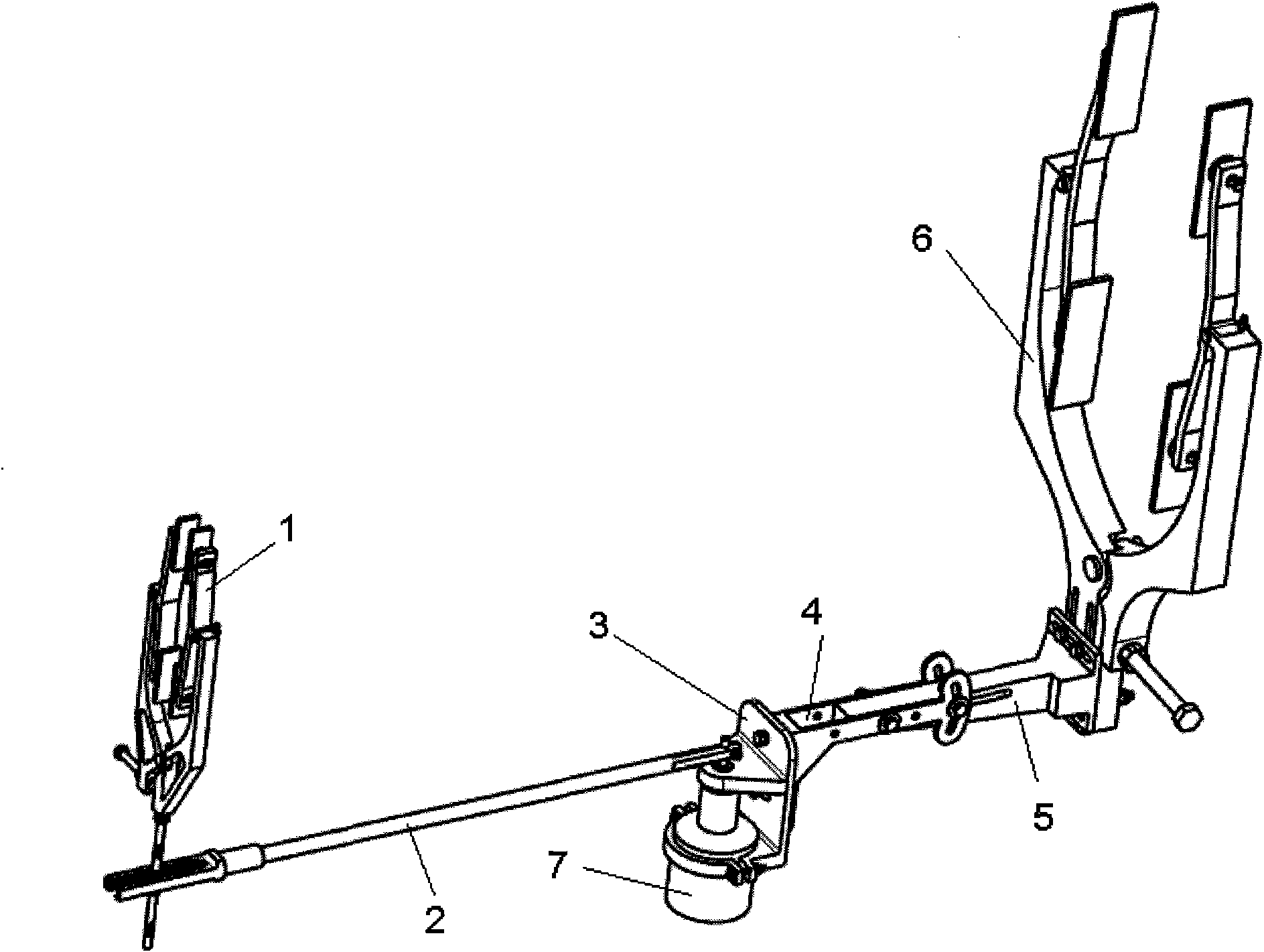
[0034]A tool for measuring the deflection angle of an aircraft rudder surface, comprising a rudder surface clamp 1, a stabilizer surface clamp 6, a strut 5, an adjustment arm 4, a sensor support 3, an angular displacement sensor 7, and a fork ear rocker arm 2.

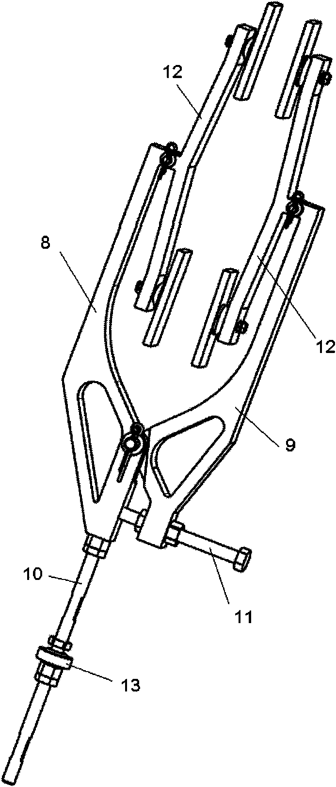
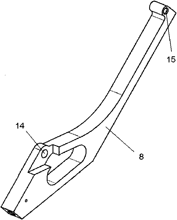
[0035] Rudder surface clip 1 comprises rudder surface main clamping rod 8, rudder surface secondary clamping rod 9, screw rod 10, two groups of rudder surface movable clamps 12, clamping bolt 11, joint bearing 13. Wherein the rudder surface movable clamp 12 comprises a rudder surface movable clamp rod 17 and two rudder surface clamp blocks 18 . The main clamping rod 8 of the rudder surface and the secondary clamping rod 9 of the rudder surface are all "3" type clamping rods, the upper part is longer, the lower part is shorter, the upper end has hinged holes 15, and the middle and lower turning...


PUM


Abstract

The invention discloses a tool and a method for measuring the deflection angle of an airplane control surface. The measuring tool comprises a control surface clip (1), a stabilizer clip (6), a brace rod (5), a regulating arm (4), a sensor support (3), an angular displacement sensor (7) and a forked rocker arm (2). The measuring process comprises the following steps: clamping the stabilizer clip (6) of the measuring tool to a force-bearing position of a vertical tail stabilizer (45), sequentially mounting the brace rod (5), the regulating arm (4), the sensor support (3), the angular displacement sensor (7) and the forked rocker arm (2) in place, clamping the control surface clip (1) to a force-bearing position of an upper rudder (46), and moving the angular displacement sensor (7) to a rotary shaft of the upper rudder (46) so as to measure the deflection angle of the control surface. The invention can be simultaneously used for measuring the deflection angle of the rudder or the elevator in the bench test or the ground built-in test of an airplane, can be directly used for measuring the deflection angle of the control surface without disassembling structural parts of the airframe, and is especially suitable for the condition that the deflection amount can not be educed for measurement by means of a link mechanism in case that the rotary shaft is arranged inside the envelope of the control surface.

Description

technical field [0001] The invention belongs to the fields of testing and machinery, and in particular relates to a tool for measuring the deflection angle of an aircraft rudder surface and a measuring method thereof. Background technique [0002] At present, in the principle and function test of the aircraft control system, the dynamic and static test of the rudder system and the elevator system are very important. In this type of test, it is necessary to measure the deflection angle of each rudder surface without exception. During the test process, the deflection angle of the rudder surface cannot be measured directly, and a mechanical linkage mechanism is required. For the on-board test, since all parts of the aircraft have been installed, it is impossible to disassemble the skin or extend the rudder surface shaft to The outside of the fuselage is directly connected to the sensor, and the measurement of the deflection angle of the rudder surface has become a difficult poi...

Claims


Application Information

Patent Timeline
Patent Type & Authority Applications(China)
IPC IPC(8): G01B21/22
Inventor 王慧薛峰牟谨刚
Owner XIAN AIRCRAFT DESIGN INST OF AVIATION IND OF CHINA
Why Eureka
Try Eureka