Method and device for testing magnetic viscosity of magnetic liquid
A magnetic liquid and testing method technology, applied in the direction of measuring devices, flow characteristics, instruments, etc., can solve the problems of large number of liquid samples, a large number of liquid samples, and high power consumption, etc., and achieve less sample consumption, convenient use, and high performance The effect of low consumption
- Summary
- Abstract
- Description
- Claims
- Application Information
AI Technical Summary
Problems solved by technology
Method used
Image
Examples
Embodiment 1
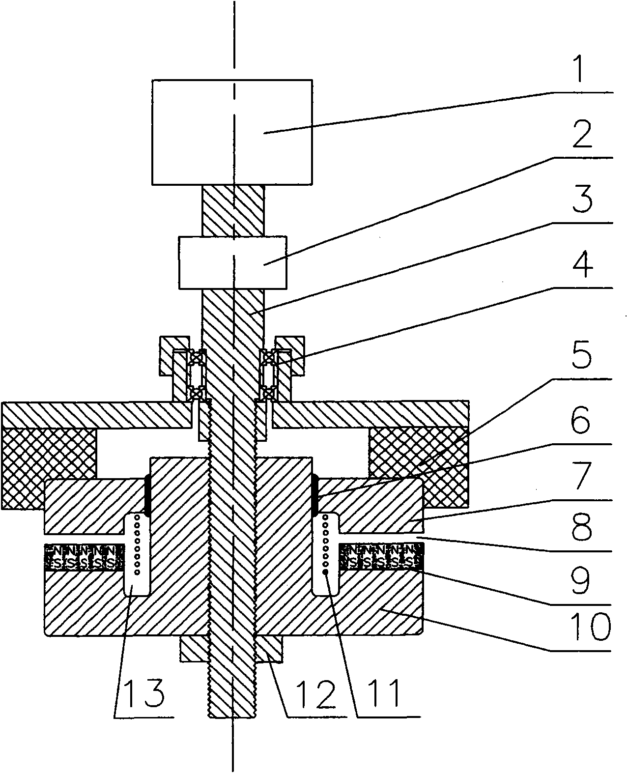
[0054] The concentric connection between the magnetically conductive fixed ring 7 and the rotating shaft 3 through the nonmagnetic centering assembly 5 is that the magnetically conductive fixed ring 7 is fixed in the nonmagnetic centering assembly 5; the described permanent magnet ring 9 is arranged on the magnetically conductive moving ring 10, the radially adjustable gap 8 is formed by the permanent magnet ring 9 and the magnetically permeable fixed ring 7, such as figure 1 shown.
Embodiment 2
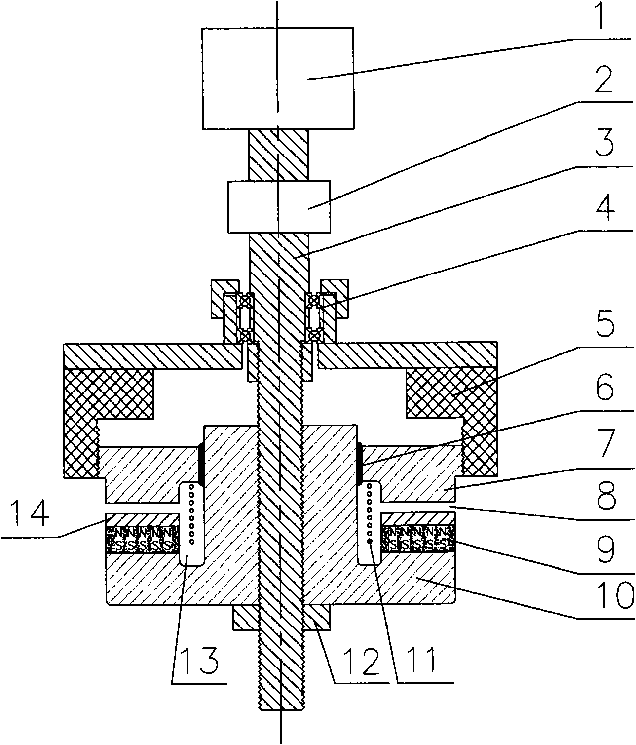
[0056] The concentric connection between the magnetically conductive fixed ring 7 and the rotating shaft 3 through the nonmagnetic centering assembly 5 is that the magnetically conductive fixed ring 7 is threaded in the nonmagnetic centering assembly 5 and can be moved up and down to adjust; adjust the radially adjustable gap 8 size; the permanent magnetic ring 9 is located on the magnetically conductive moving ring 10, and the permanent magnetic ring 9 is provided with a pole shoe ring, 14 which protects the magnetically conductive effect, and the pole shoe ring 14 and the magnetically conductive fixed ring 7 to form a radially adjustable gap 8, such as image 3 shown.
Embodiment 3
[0058] The concentric connection between the magnetically conductive fixed ring 7 and the rotating shaft 3 through the non-magnetic centering assembly 5 is the same as that of embodiment 1, and the magnetically conductive fixed ring 7 is also fixed in the nonmagnetic centering assembly 5; the permanent magnetic ring 9 is located below the magnetically conductive fixed ring 7, and the radially adjustable gap 8 is formed by the permanent magnetic ring 9 and the magnetically conductive moving ring 10, such as Figure 4 shown.
PUM
 Abstract
Description
Claims
Application Information
 - R&D
- Intellectual Property
- Life Sciences
- Materials
- Tech Scout
- Unparalleled Data Quality
- Higher Quality Content
- 60% Fewer Hallucinations
Browse by: Latest US Patents, China's latest patents, Technical Efficacy Thesaurus, Application Domain, Technology Topic, Popular Technical Reports.
© 2025 PatSnap. All rights reserved.Legal|Privacy policy|Modern Slavery Act Transparency Statement|Sitemap|About US| Contact US: help@patsnap.com


