In-wheel motor drive device

A technology of in-wheel motor and driving device, which is applied in the directions of gear transmission, electromechanical device, electric device, etc., can solve the problems of decreased durability and lubricating performance of the in-wheel motor driving device 101, and achieve excellent durability and restrain temperature rise. , the effect of high reliability

Inactive Publication Date: 2011-02-02
NTN CORP +1
View PDF5 Cites 31 Cited by
  • Summary
  • Abstract
  • Description
  • Claims
  • Application Information

AI Technical Summary

Problems solved by technology

[0006] At this time, the lubricating oil becomes high temperature due to the friction loss of the deceleration unit 105, iron loss of the motor unit 103,

Method used


Image

  • In-wheel motor drive device
  • In-wheel motor drive device
  • In-wheel motor drive device

Examples


Embodiment Construction

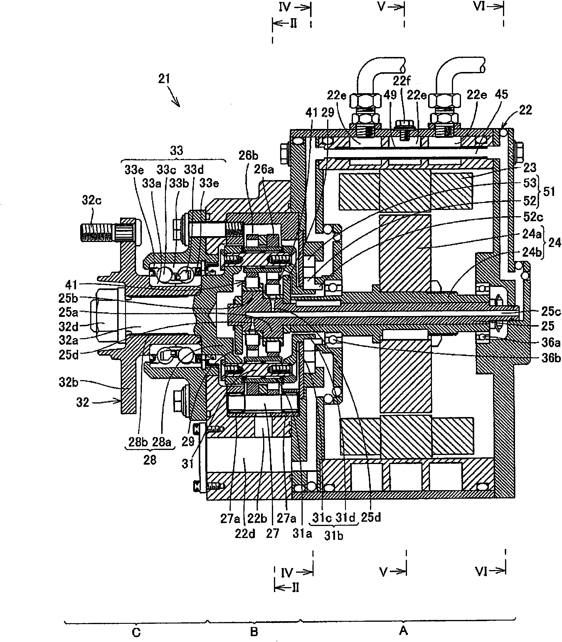
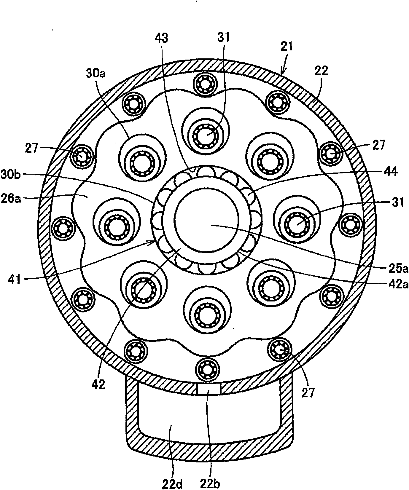
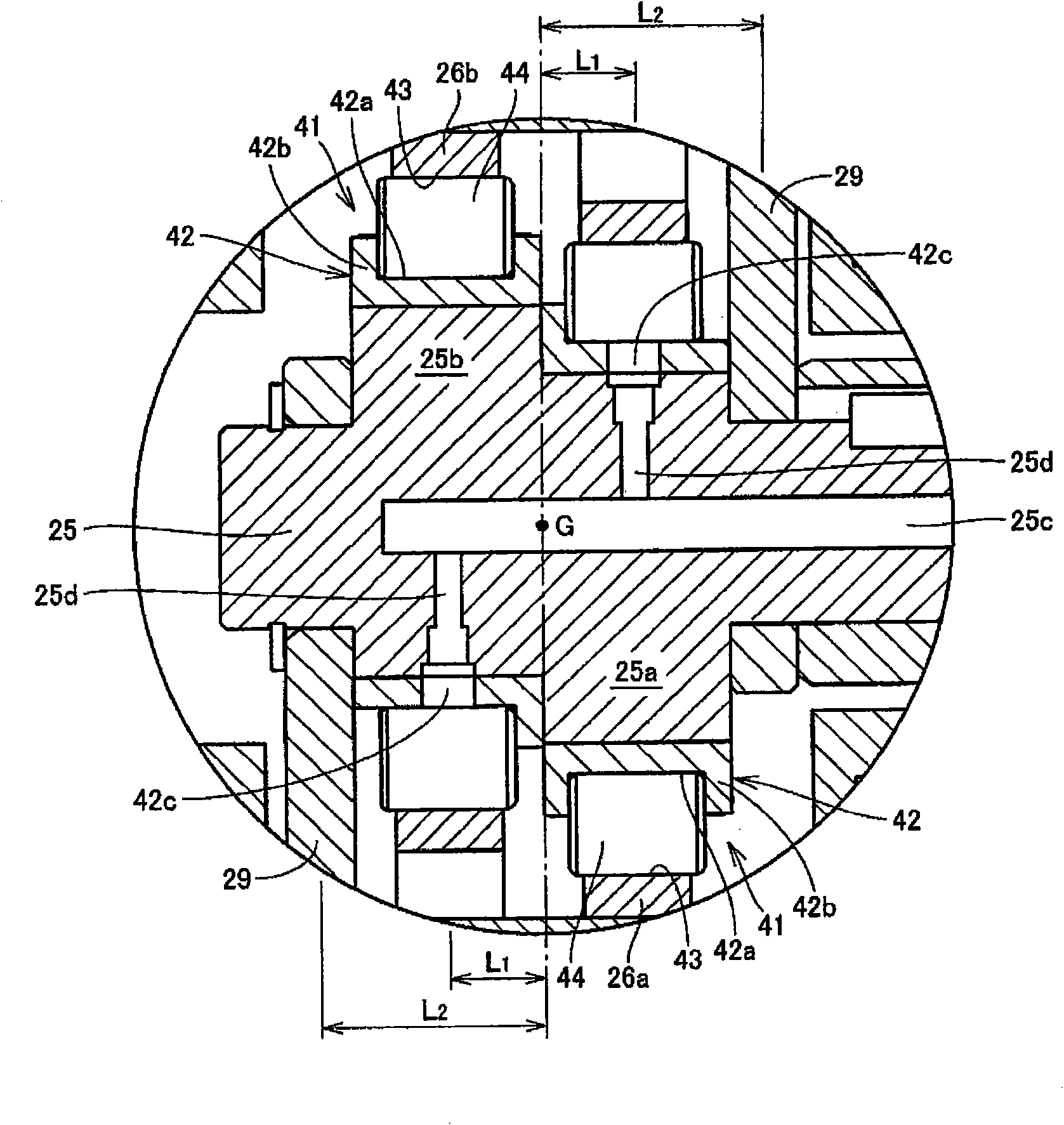
[0027] refer to Figure 1 to Figure 9 , the in-wheel motor drive device 21 according to one embodiment of the present invention will be described.

[0028] Figure 8 is a schematic diagram of an electric vehicle 11 employing an in-wheel motor drive device 21 according to an embodiment of the present invention, Figure 9 It is a schematic view of the electric vehicle 11 viewed from the rear. refer to Figure 8 The electric vehicle 11 includes a chassis 12 , front wheels 13 as steering wheels, rear wheels 14 as drive wheels, and an in-wheel motor driving device 21 that transmits driving force to the left and right rear wheels 14 . refer to Figure 9 , the rear wheel 14 is accommodated inside the wheel shell 12a of the chassis 12, and is fixed to the lower portion of the chassis 12 via a suspension device (suspension) 12b.

[0029] The suspension device 12b supports the rear wheel 14 by a cantilever extending left and right, and absorbs vibration received by the rear wheel 1...


PUM


Abstract

An in-wheel motor drive device (21) has a motor section (A), a reduction section (B), a wheel hub (C), and a reduction section lubricating mechanism for supplying lubricating oil to the reduction section. The reduction section lubricating mechanism has a lubricating oil path (25c), a lubricating oil supplying opening (25d), a lubricating oil discharging opening (22b), a circulating oil path (45) passing through the inside of a casing (22) to interconnect the lubricating oil discharging opening (22b) and the lubricating oil path (25c) and circulating lubricating oil, which is discharged from the lubricating oil discharging opening (22b), to the lubricating oil path (25c), a cooling water path (22e) provided at that position in the casing (22) which is in contact with the circulating oil path (45) and cooling lubricating oil passing through the circulating oil path (45), and a partitioning member (49) mounted at a position at which the circulating oil path (45) and the cooling water path (22e) are in contact with each other and separating the paths from each other.

Description

technical field [0001] The present invention relates to an in-wheel motor driving device in which an output shaft of a motor is connected to a hub of a wheel through a speed reducer. Background technique [0002] A conventional in-wheel motor drive device 101 is described in, for example, Japanese Patent Application Laid-Open No. 2006-258289. refer to Figure 10 , the wheel hub motor driving device 101 has: the motor part 103 that generates the driving force inside the housing 102 installed on the vehicle body; the wheel hub bearing part 104 connected to the wheel; transmission to the deceleration section 105 . [0003] In the in-wheel motor driving device 101 configured as described above, a low-torque and high-rotational motor is used for the motor unit 103 from the viewpoint of device compactness. On the other hand, the wheel hub bearing portion 104 requires a large torque to drive the wheel. Therefore, a compact cycloidal speed reducer capable of obtaining a high spee...

Claims


Application Information

Patent Timeline
IPC IPC(8): H02K7/116F16H57/02F16H57/04B60K7/00
CPCB60K2007/0092F16H57/0476H02K5/20F16H57/0424Y02T10/641F16H1/32H02K5/1732B60K17/043H02K7/116B60K17/046F16H57/0412F16H57/043B60K2007/0038F16H57/0471B60K17/356H02K9/19B60K7/0007B60L1/02B60L3/0061B60L7/12B60L15/2009B60L2220/44B60L2240/36B60L2240/421B60L2240/423B60L2240/425Y02T10/72B60L50/52Y10T74/2189Y02T10/64Y02T10/70H02K5/203
Inventor 山本宪牧野智昭铃木稔饭尾能将
Owner NTN CORP
Why Eureka
Try Eureka