Upper polishing disk of polishing machine

A technique for polishing machines and polishing discs, which is applied in abrasives, metal processing equipment, manufacturing tools, etc. It can solve the problems of no temperature control and uncontrollable changes in the temperature of polishing discs, etc., and achieve a reliable cooling effect

Inactive Publication Date: 2011-02-09
LANZHOU RAPID INDGRPCO +1
View PDF7 Cites 10 Cited by
  • Summary
  • Abstract
  • Description
  • Claims
  • Application Information

AI Technical Summary

Problems solved by technology

[0003] Previously, the polishing disc of the double-sided polishing machine used an integral structure without a special temperature control device. The heat generated during the polishing process was mainly taken away by the polishing liquid, which was passive cooling, and the temperature change of the polishing disc was uncontrollable.

Method used


Image

  • Upper polishing disk of polishing machine
  • Upper polishing disk of polishing machine
  • Upper polishing disk of polishing machine

Examples


Embodiment 1

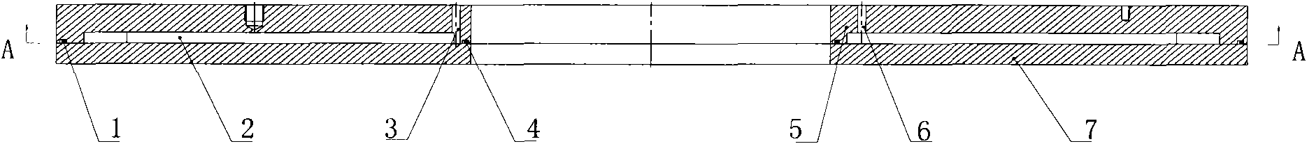
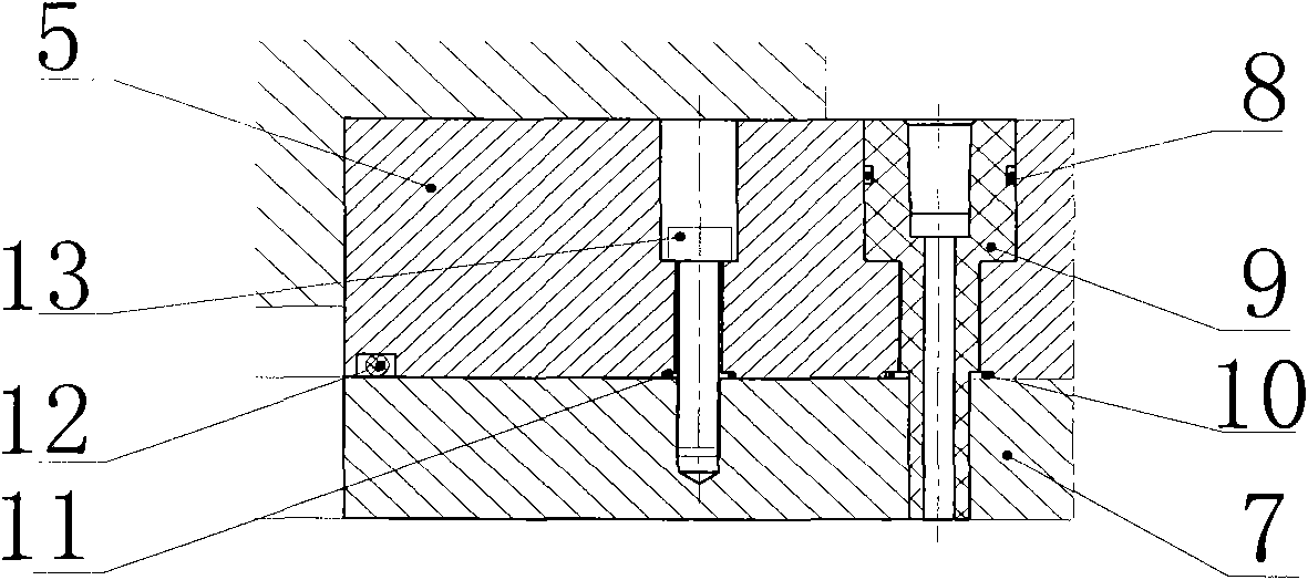
[0018] Example 1: see figure 1 , figure 2 , image 3 , an upper polishing disc of a polishing machine, including an upper disc working disc 7, an upper disc water cooling disc 5 is arranged above the upper disc working disc 7, and a cavity is formed between the upper disc working disc 7 and the upper disc water cooling disc 5 2. A water inlet 3 and a water outlet 6 are provided on the upper water cooling plate 5, and the water inlet 3 and the water outlet 6 communicate with the cavity 2 respectively.

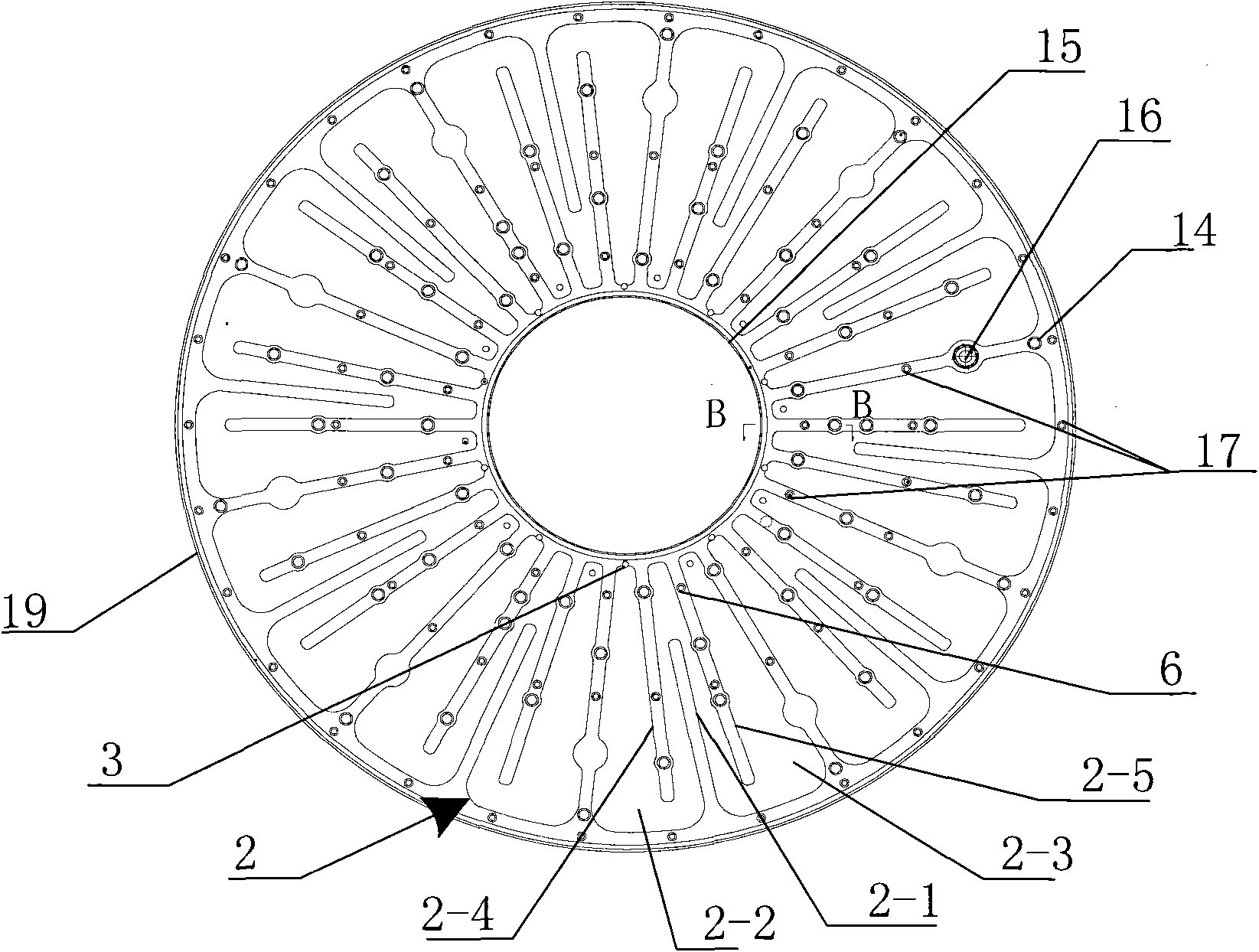
[0019] A cavity 2 is formed between the upper plate water cooling plate 5 and the upper plate working plate 7, and the cavity 2 is provided with several concave fan-shaped areas on the upper plate water cooling plate 5 to form several Fan-shaped cooling cavity. Each sunken fan-shaped area is divided into two interconnected sunken water inlet areas 2-2 and water outlet areas 2-3 by the protruding dividing rib 2-1. The water outlet 3 is provided with a water outlet 6 in the w...


PUM


Abstract

The invention relates to a structure of a silicon chip grinding machine or a polishing machine, in particular to the structure of an upper positioning disk of the silicon chip grinding machine or the polishing machine. The upper polishing disk of the polishing machine comprises an upper working disk (7) and is mainly characterized in that an upper water cooling disk (5) is arranged above the upper working disk (7), a cavity (2) is formed between the upper working disk (7) and the upper water cooling disk (5), and a water inlet (3) and a water outlet (6) are arranged on the upper water cooling disk (5) and respectively communicated with the cavity (2). The structure has the advantages that the special water cooling disk structure consists of a plurality of independent fan-shaped regional cavities, each fan-shaped regional cavity has the respective water inlet and the water outlet, and a waterway is designed to be a labyrinth, thereby preventing cooling water from taking a short cut, realizing that the cooling water can only flow out of the water outlet after the cavity is full of the cooling water, ensuring that the cooling water can carry out sufficient cooling of the polishing disk, taking away heat produced by processing in time, playing a forced cooling role for the polishing disk and being more reliable in comparison with the traditional passive cooling.

Description

Technical field: [0001] The invention relates to the structure of a silicon wafer grinder or polishing machine, in particular to the structure of a polishing disc on the silicon wafer grinder or polisher. Background technique: [0002] For thin and brittle materials, especially the upper polishing disc of the silicon wafer polishing machine, due to the large amount of heat generated during the polishing process, the temperature change will inevitably cause the deformation of the polishing disc, which will affect the processing quality, so the temperature of the polishing disc must be strictly controlled . In recent years, the size of silicon wafers for IC processing tends to be larger in diameter, and the quality requirements for the morphology of silicon wafers are becoming more and more stringent. For polishing equipment used for double-sided polishing of silicon wafers, the deformation of the polishing disc must be strictly controlled. The water cooling structure of the ...

Claims


Application Information

Patent Timeline
Patent Type & Authority Applications(China)
IPC IPC(8): B24D7/18
Inventor 金万斌李娟梁春
Owner LANZHOU RAPID INDGRPCO
Why Eureka
Try Eureka