Energy-dissipating hangar tunnel and energy-dissipating supporting base thereof

An energy dissipation and shed tunnel technology, applied in the field of shed tunnels, can solve the problems of increasing the impact resistance of shed tunnels, increasing the construction cost of shed tunnels, and difficult construction of shed tunnels, and achieving the effects of light weight, simple structure and low cost.

Inactive Publication Date: 2011-02-09
陈洪凯 +2
View PDF3 Cites 29 Cited by
  • Summary
  • Abstract
  • Description
  • Claims
  • Application Information

AI Technical Summary

Problems solved by technology

Most of the sheds in the prior art are rigid structures, and the huge energy of dangerous rocks and falling rocks is rigidly transmitted to all parts of the shed, causing a huge impact on the entire shed
In order to improve the impact resistance of the shed, it is often necessary to increase the impact resistance of each part of the shed, which brings difficulties to the construction of the shed and increases the construction cost of the shed.

Method used


Image

  • Energy-dissipating hangar tunnel and energy-dissipating supporting base thereof
  • Energy-dissipating hangar tunnel and energy-dissipating supporting base thereof
  • Energy-dissipating hangar tunnel and energy-dissipating supporting base thereof

Examples


Embodiment 1

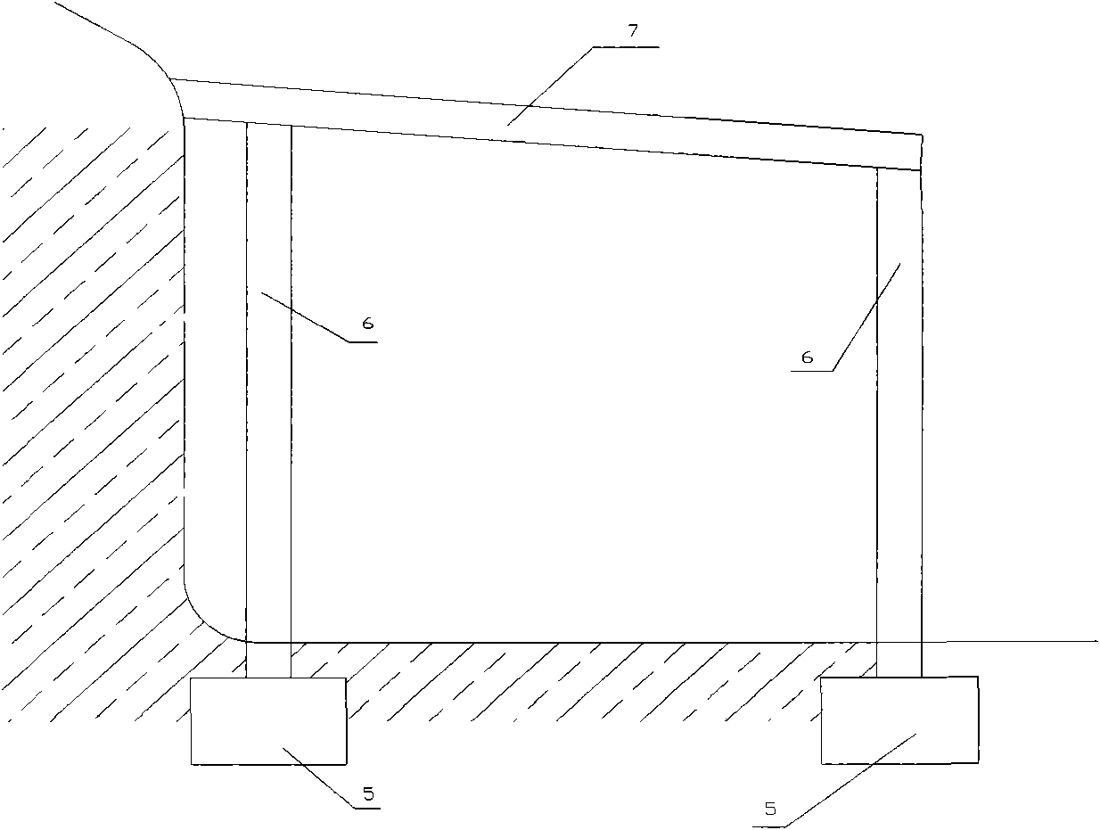
[0012] Embodiment 1 The structure of the energy-dissipating shed

[0013] attached figure 2 The cross-sectional schematic diagram of the energy dissipation shed hole, as can be seen from the figure, the energy dissipation shed hole includes pile foundations, pillars and protective sheds, and an energy dissipation support is arranged between the pillars and the protective shed. The setting of the energy-dissipating support enables the huge energy of dangerous rocks and falling rocks to be absorbed by the energy-dissipating support, which reduces the impact on the pillars and pile foundations, and improves the impact resistance of the pillars and pile foundations.

Embodiment 2

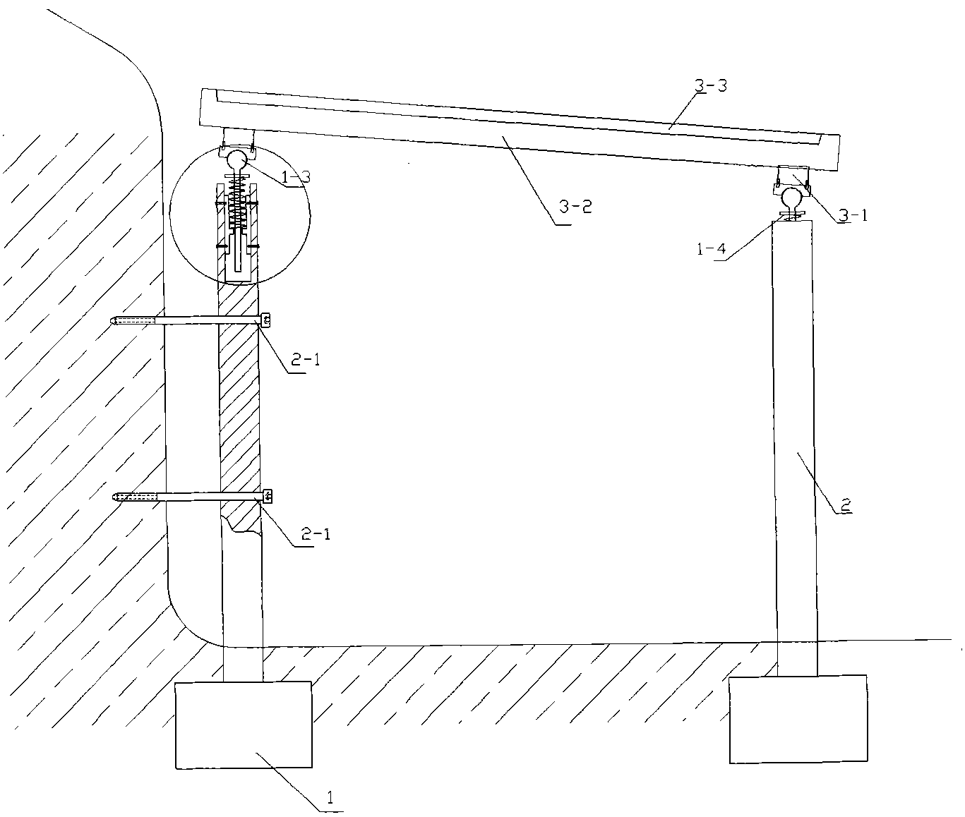
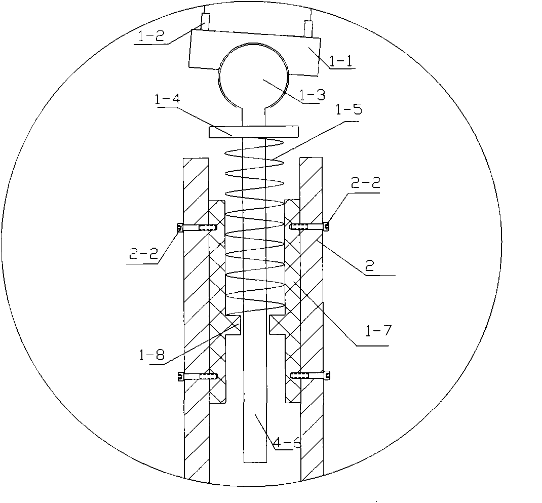
[0014] Embodiment 2 Structure of Energy Dissipating Support

[0015] attached image 3 Schematic diagram of the structure of the energy dissipation support. It can be seen from the figure that the structure of the energy dissipation support from top to bottom is: rotating top plate connecting plate 1-1, connecting bolt 1-2, steel ball tenon 1-3, spring 1-4, The load transfer bracket 1-5, the spring guide rod 1-6 and the load transfer steel plate 1-7; the load transfer steel plate 1-7 is a cylindrical structure with an annular positioning ring 1-8 inside.

[0016] Among them, the load-transmitting steel plate 1-7 is fixed on the inner side of the pillar 2 by the bolt 2-2, and the spring guide rod 1-6 passes through the middle section of the load-transmitting steel plate 1-7 and is defined as the ring 1-8 along the middle of the load-transmitting steel plate 1-7. The axis moves up and down, the spring guide rod 1-6 is covered with a spring 1-4, the lower end of the spring 1-4 i...

Embodiment 3

[0019] Embodiment 3 Installation of energy dissipation shed hole and its energy dissipation support

[0020] attached Figure 4 The three-dimensional schematic diagram of the installation of the energy-dissipating shed and the energy-dissipating support. It can be seen from the figure that the installation of the energy-dissipating shed and its energy-dissipating support includes the following steps: measure the terrain, determine the position of the pile foundation on both sides of the road along the road extension direction, Excavate the foundation and pour the pile foundation 1 on site or fill the prefabricated pile foundation 1 .

[0021] Install prefabricated columns 2 or cast-in-place columns 2 on the pile foundation, the height of a row of columns 2 near the mountain side is higher than that of the row of columns 2 on the other side, and reserve anchor rods on the row of columns 2 near the mountain side 2-1 guide hole; through the anchor rod guide hole 2-3 reserved in ...


PUM


Abstract

The invention discloses an energy-dissipating hangar tunnel and an energy-dissipating supporting base thereof. The energy-dissipating supporting base comprises a spring guide rod, wherein the spring guide rod is sleeved in the spring; a protective shed is supported by the upper end of the spring guide rod; the lower end of the spring guide rod passes through a load-transferring steel plate; the upper end of the spring is fixed on the bottom surface of a load-transferring bracket; the lower end of the spring is supported on the load-transferring bracket; and the load-transferring steel plate is fixed on a support. The energy-dissipating hangar tunnel and the energy-dissipating supporting base thereof have the innovative points that: the energy-dissipating supporting base is simple in structure, low in cost, light in weight, high in rigidity and high in buffer capacity when impacted violently; and the energy-dissipating supporting base is suitable for performing energy dissipation on facilities easily subjected to violent impact, such as the hangar tunnel and the like.

Description

technical field [0001] The invention relates to a shed cave used for protecting dangerous rocks and falling rocks in highway construction, in particular to an energy dissipation shed cave and an energy dissipation support. technical background [0002] my country is a mountainous country, with mountains and hills accounting for more than 2 / 3 of the country's total land area. It is one of the countries with the most severe rock collapse disasters in the world, especially in western regions such as Tibet, Sichuan, Gansu, Xinjiang, Yunnan, and Chongqing. There are hundreds of millions of dangerous rock masses with serious safety hazards along highways, mines and urban areas. In the process of highway construction, it is inevitable to encounter landforms along rivers and mountains. At present, highway construction is mainly based on excavation of road cuttings. In areas along rivers and mountains, high and large cut slopes will inevitably appear. As a result, geological disaster...

Claims


Application Information

Patent Timeline
Patent Type & Authority Applications(China)
IPC IPC(8): E01F7/04E04B1/36
Inventor 陈洪凯唐红梅王林峰
Owner 陈洪凯
Why Eureka
Try Eureka