

Lens barrel and imaging device
A technology of lens barrel and cam, applied in installation, optics, instruments, etc., can solve the problems of increased sliding resistance between cam pins and cam grooves, increased cam pin size, etc., and achieve the effect of ensuring strength
- Summary
- Abstract
- Description
- Claims
- Application Information
AI Technical Summary
Problems solved by technology
Method used
Image

Examples
no. 1 approach
[0058] (1: Structure of digital camera)
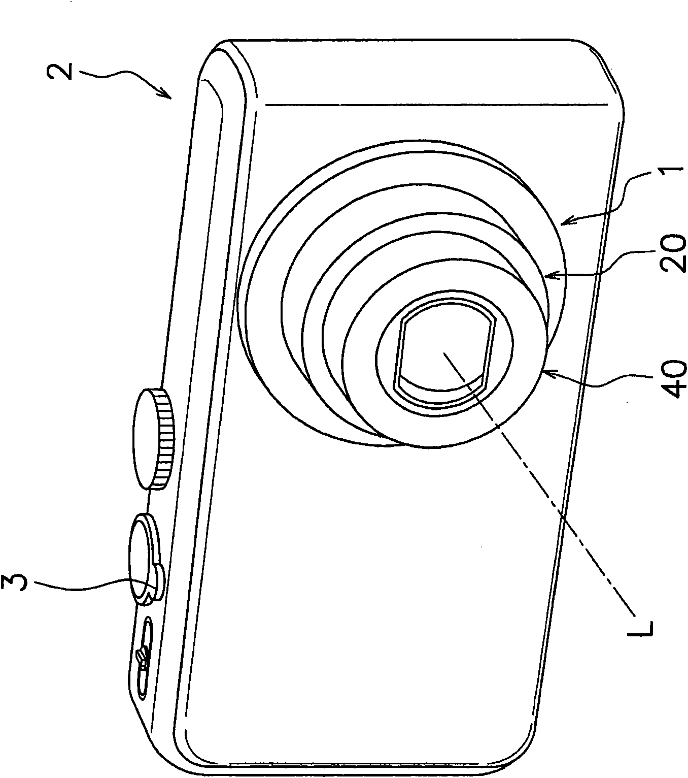
[0059] like figure 1 As shown, a lens barrel 1 is mounted on a digital camera 2 (an example of an imaging device). The lens barrel 1 includes various lenses such as a varifocal lens and a focus lens, an imaging element that converts incident light into an electrical signal and outputs it, and the like. In addition, the digital camera 2 is a digital still camera and is an example of an imaging device. As the imaging device, in addition to digital still cameras, optical devices such as digital video cameras and mobile phones with cameras are also conceivable.
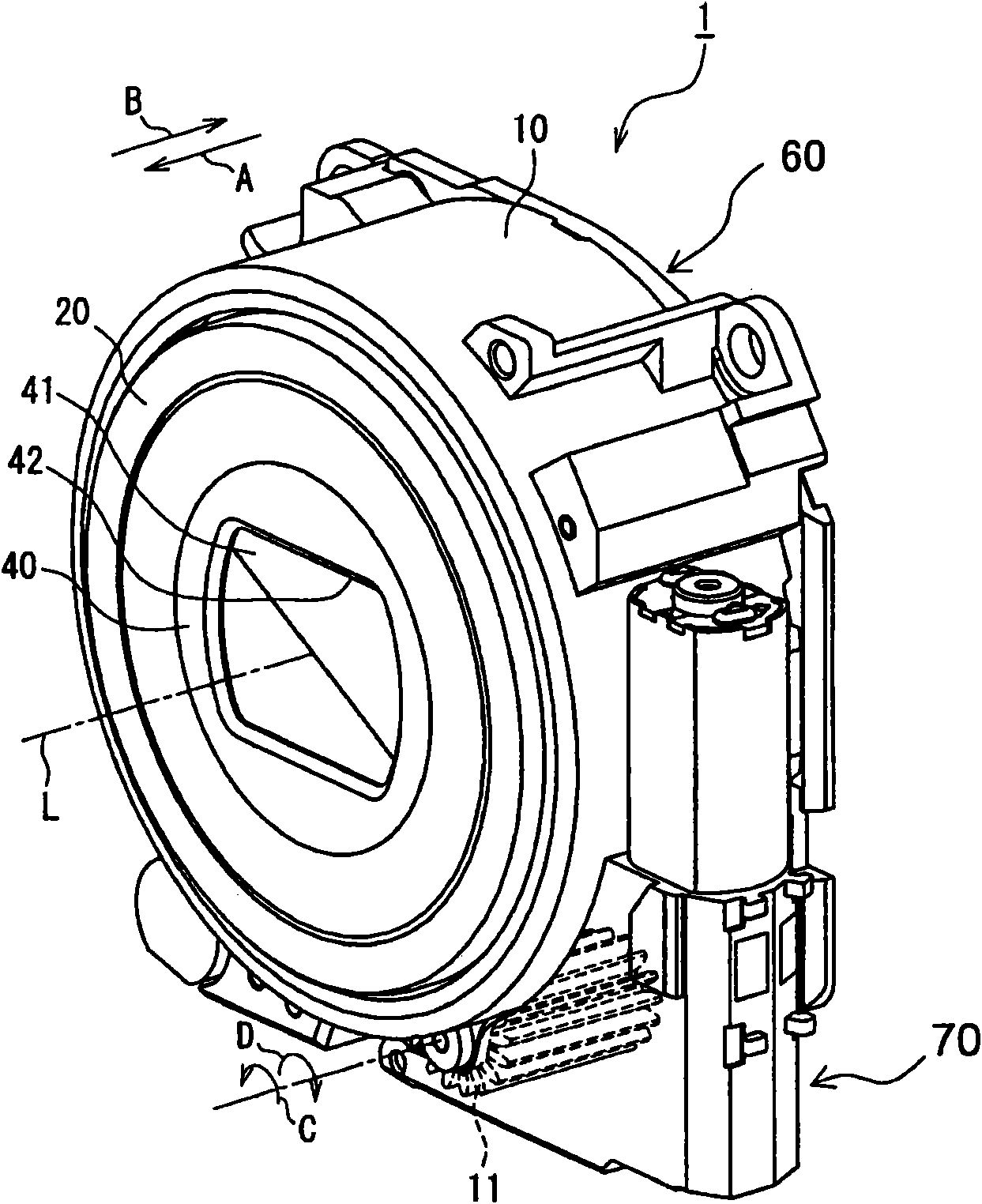
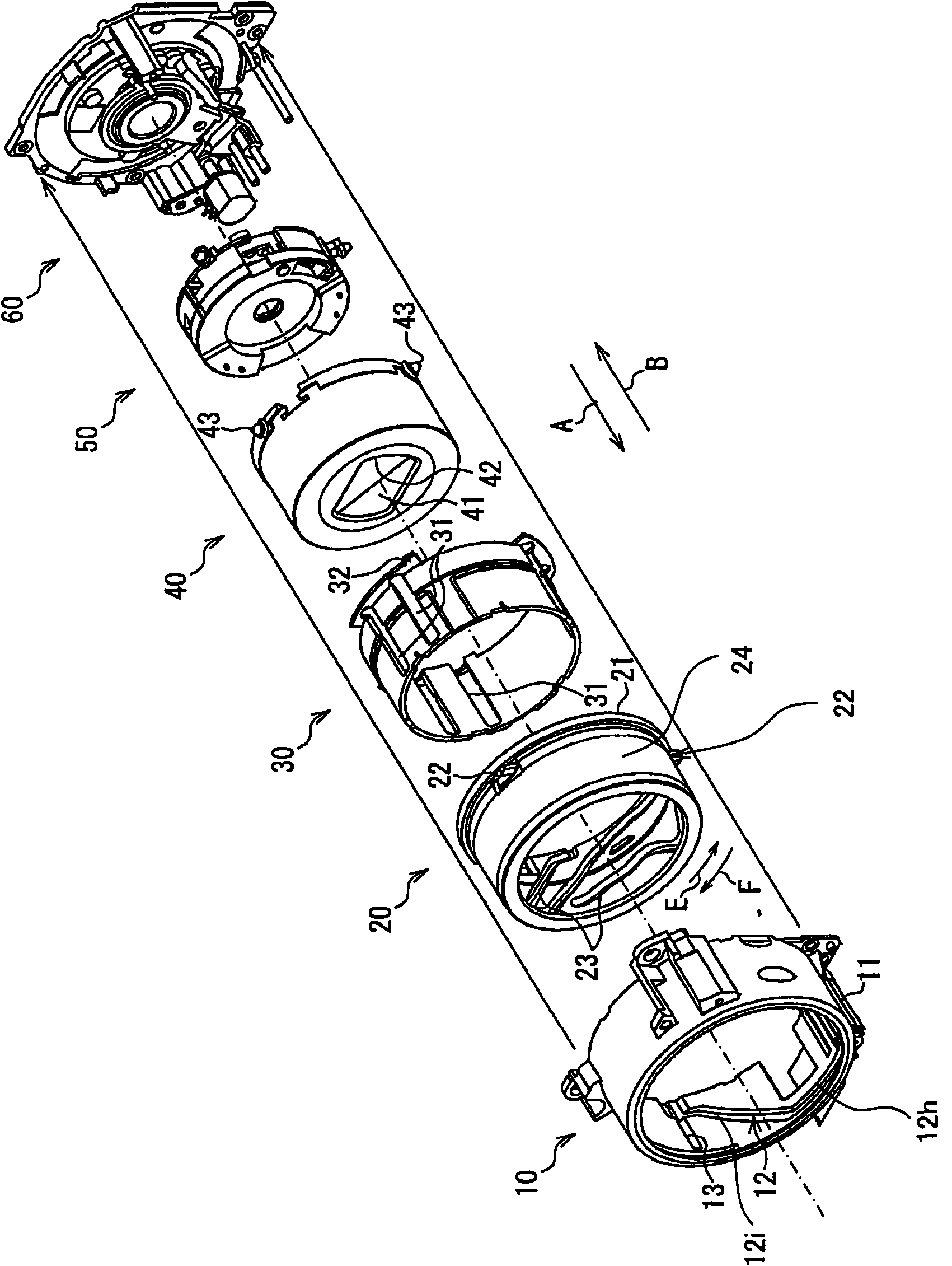
[0060] like figure 2 and image 3 As shown, the lens barrel 1 has an optical system (not shown), an imaging element (not shown), a motor unit 70, a fixed frame 10 (an example of a first support frame), a drive frame 20 (an example of a second support frame) ), straight into frame 30 (refer to image 3 ), the first lens group unit 40, the second lens group unit 50 (refer to ...
no. 2 approach
[0107] In the first embodiment, the cam follower 22 has the first cam portion 22a, the second cam portion 22b, and the connection portion 22c, but Figure 9 (A)~ Figure 9 The cam follower shown in (C) can also reduce sliding resistance.
[0108] like Figure 9 (B) and Figure 9As shown in (C), the drive frame 120 has the drive frame main body 24 and the cam follower 122 described in the first embodiment. The cam follower 122 (an example of a cam member) is made of metal, and is embedded in the drive frame main body 24, for example. The cam follower 122 has an embedding portion 122a, a washer 122b, a sliding portion 122c, and a step portion 122d. The embedded portion 122 a is embedded in the drive frame main body 24 . The sliding portion 122c and the stepped portion 122d are inserted into the cam groove 112 (an example of a cam guide groove). The sliding portion 122c is arranged to be slidable with the cam groove 112 . The stepped portion 122d is arranged with a gap G3 ...
no. 3 approach
[0113] and, Figure 10 (B) and Figure 10 The cam follower 222 shown in (C) can also reduce sliding resistance.
[0114] like Figure 10 (B) and Figure 10 As shown in (C), the drive frame 220 has the drive frame main body 24 and the cam follower 222 described in the first embodiment. The cam follower 222 (an example of a cam member) has a base portion 222a, a slide portion 222b, and a step portion 222c. The cam follower 222 is integrally formed with the drive frame main body 24 made of resin. The cam follower 222 is inserted into the cam groove 212 (an example of a cam guide groove). The sliding portion 222b is arranged to be slidable with the cam groove 212 . The stepped portion 222c is arranged with a gap G4 between the cam groove 112 and the cam groove 112 .
[0115] Specifically, the stepped portion 222c has a base portion 222e protruding outward in the radial direction from the drive frame main body 24, and an intermediate portion 222f connecting the base portion ...
PUM
 Abstract
Description
Claims
Application Information