Drainage device for lacrimal sac operation

A lacrimal sac and drainage tube technology, applied in the field of lacrimal sac surgical drainage devices, can solve problems such as prolonged operation time, reduced drainage effect, lacrimal canalicular obstruction, etc., and achieves the effects of shortened instrument operation time, reasonable device design, and fast and smooth drainage.

Inactive Publication Date: 2012-08-22
SHANDONG KAISITE MEDICAL APP & INSTR
View PDF3 Cites 0 Cited by
  • Summary
  • Abstract
  • Description
  • Claims
  • Application Information

AI Technical Summary

Problems solved by technology

However, most patients with the above-mentioned diseases are accompanied by obstruction of lacrimal canaliculi. At this time, simple dacryocystorhinostomy cannot solve the problem of obstruction, so total lacrimal duct intubation is required for drainage treatment
Yet the problem that this operation exists is, when carrying out lacrimal canaliculus catheter intubation, must pass through the central hole of the anastomotic drainage tube to enter the nasal cavity, and this has just caused the space of the central hole of the anastomotic drainage tube to be squeezed, making the drainage effect Reduce the operation time, prolong the operation time, and easily lead to poor operation results, often requiring a second operation, which brings greater pain to the patient. At the same time, the drainage tube used in the operation must use a nasal endoscope to perform stoma and placement , so it cannot be used for open dacryocystorhinostomy, and it is more difficult to place during surgery, so that the treatment of total lacrimal cannulation cannot achieve the best effect according to the patient's condition

Method used


Image

  • Drainage device for lacrimal sac operation
  • Drainage device for lacrimal sac operation
  • Drainage device for lacrimal sac operation

Examples


Embodiment

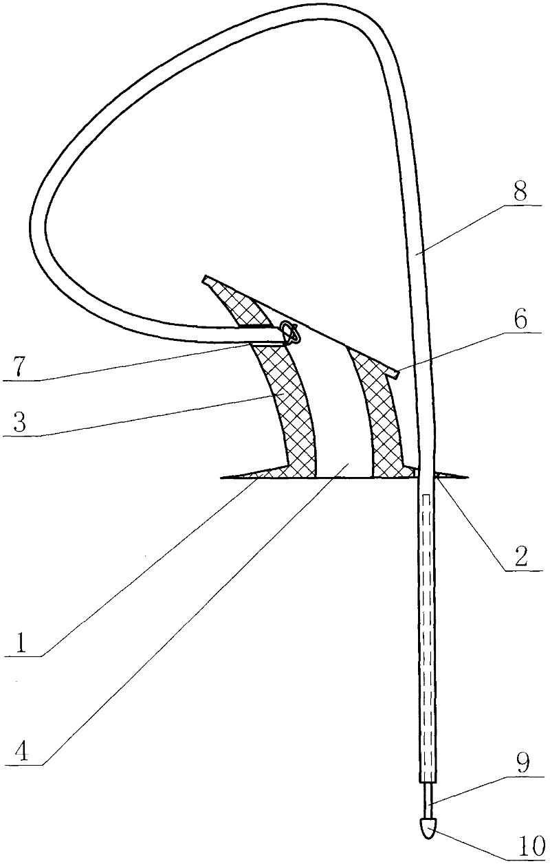
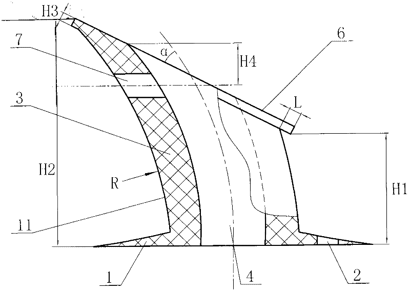
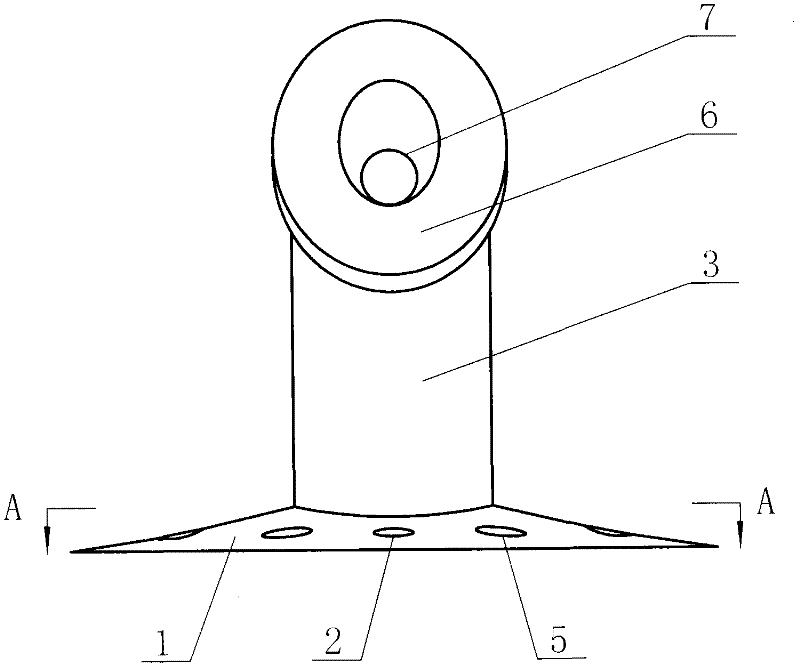
[0009] The drainage device for lacrimal sac surgery according to the present invention has a drainage tube 11, the drainage tube 11 is connected with the insertion tube 8, a metal rod 9 is installed at one end of the insertion tube 8, a ball 10 is arranged at the end of the metal rod 9, and the drainage tube 11 A base 1 is provided, and a pipe body 3 is arranged in the middle of the base 1. The pipe body 3 has an inclination angle relative to the base 1, so that the pipe body 3 is arc-shaped. The arc radius R of the pipe body 3 is 20-22 mm, and the center of the pipe body 3 A drainage cavity 4 is set up at the site, and the top end surface of the tube body 3 is an inclined plane 6, and the angle α between the inclined plane 6 and the center line of the drainage cavity 4 is 30°-40°, and the top end of the drainage cavity 4 is elliptical. The outer wall is columnar with a high outer wall and a low outer wall, and the dimensions within the range of 360° determined by the major axi...


PUM


Abstract

The invention discloses a drainage device for a lacrimal sac operation, comprising a drainage tube. The drainage tube is connected with an implanting tube which is internally provided with a metal rod at one end, a sphere is arranged at one end of the metal rod, the drainage tube is provided with a base, a tube body is arranged in the middle of the base and forms an inclined angle relative to thebase so that the tube body is in an arc shape, the center part of the tube body is provided with a drainage cavity, the tube body has an inclined top end surface, the drainage cavity has an elliptical top end, the outer wall of the tube body is the shape of a column formed by a high outer wall and a lower outer wall, the size defined by the long axis and the short axis of the inclined surface in a range of 360 degrees is larger than the outer wall diameter of the tube body, a first through hole is arranged at the upper part of the high outer wall of the tube body, the implanting tube is mounted in the first through hole, and one end of the implanting tube, which is provided with the metal rod, penetrates through a second through hole on the base. The invention is suitable for the drainagetreatment on patients with a nasolacrimal canal obstruction syndrome, chronic dacryocystitis syndrome, and the like accompanied with lacrimal canaliculi obstruction syndrome through whole lacrimal passage intubation.

Description

technical field [0001] The invention relates to a medical device, which is a lacrimal sac surgical drainage device specially used for nasolacrimal duct obstruction and lacrimal duct obstruction operation. Background technique [0002] When suffering from chronic dacryocystitis, nasolacrimal duct obstruction, dacryocystor mucocele and other diseases, the most effective treatment method is surgical treatment. The current surgical method is to treat the above diseases by performing dacryocystorhinostomy. However, most patients with the above-mentioned diseases are accompanied by obstruction of the lacrimal canaliculus. At this time, the simple dacryocystorhinostomy cannot solve the obstruction problem, so total lacrimal duct intubation is required for drainage treatment. Yet the problem that this operation exists is, when carrying out lacrimal canaliculus catheter intubation, must pass through the central hole of the anastomotic drainage tube to enter the nasal cavity, and this...

Claims


Application Information

Patent Timeline
Patent Type & Authority Patents(China)
IPC IPC(8): A61F9/007A61F2/82A61M1/00
Inventor 王勤孙业张森刘文冰
Owner SHANDONG KAISITE MEDICAL APP & INSTR
Why Eureka
Try Eureka