Traveling crane position tracking device based on radio frequency identification

A driving position and tracking device technology, applied in the field of driving position tracking, can solve the problems of heavy installation workload and difficulty in obtaining high positioning accuracy, and achieve the effects of reducing installation workload, improving guiding significance, and eliminating positioning errors

Inactive Publication Date: 2011-02-16
SOUTHEAST UNIV
View PDF8 Cites 17 Cited by
  • Summary
  • Abstract
  • Description
  • Claims
  • Application Information

AI Technical Summary

Problems solved by technology

The traditional method of measuring displacement based on the rotation of the mechanical wheel has high measurement accuracy, but is affected by factors such as mechanical wheel slippage and mechanical inertia, resulting in a large cumulative error in the long-term operation of the method; the current radio frequency identification positioning technology is used in high-speed trains Good application results have been achieved in different fields such as positioning and production tool positioning. This method adopts a non-contact identification method with fast reading speed and high reliability. However, in order to obtain high positioning accuracy, it is necessary to ensure that the track is laid dense Radio frequency identification (RFID) electronic tags, the installation workload is relatively large, and it is difficult to obtain high positioning accuracy

Method used


Image

  • Traveling crane position tracking device based on radio frequency identification
  • Traveling crane position tracking device based on radio frequency identification
  • Traveling crane position tracking device based on radio frequency identification

Examples


Embodiment Construction

[0024] The application of a driving position tracking device of the present invention in the steel coil storage area of ​​a steel plant will be taken as an example to further describe the present invention in detail below.

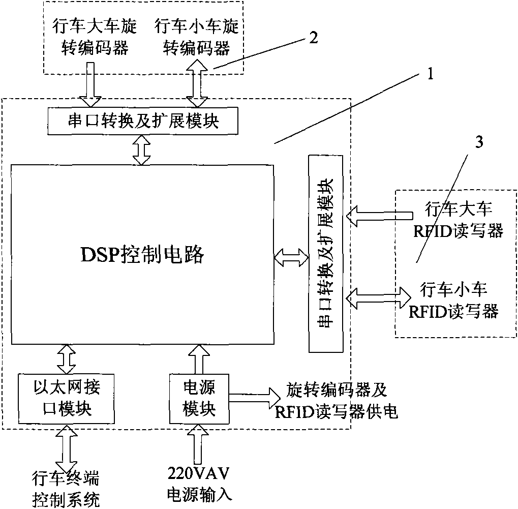
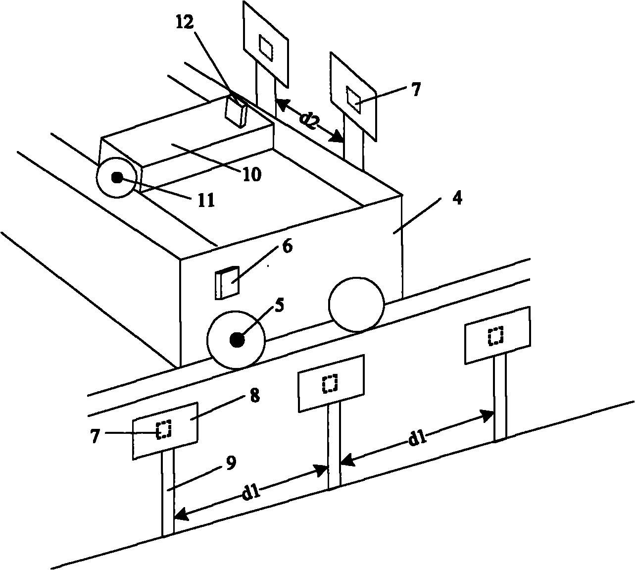
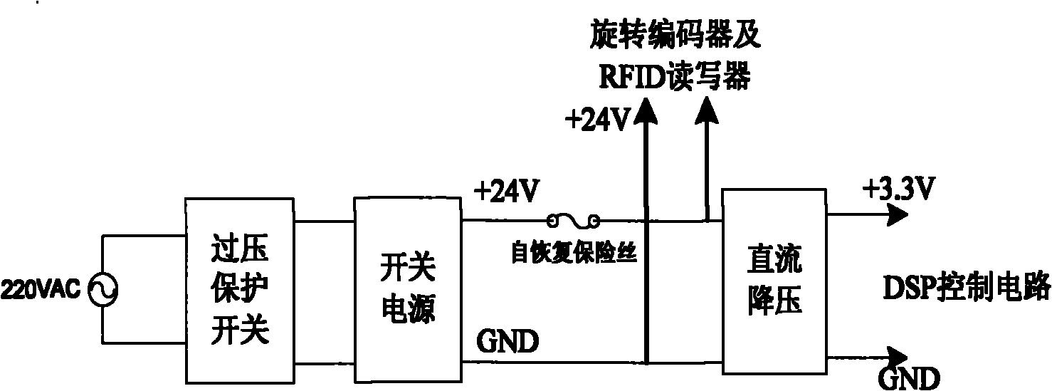
[0025] Such as figure 1 , figure 2 As shown, the device consists of three parts: main controller 1, position detection device 2, and position calibration device 3. The main controller 1 includes a DSP control circuit, a power supply module, a serial port conversion and expansion module, and an Ethernet interface module. The position detection device 2 includes a rotary encoder and a rotary encoder communication cable. The position calibration device 3 includes an RFID cart reader, an RFID trolley reader, an RFID electronic tag, and a tag fixing bracket.

[0026] 1. Main controller part

[0027] The main controller part is placed in the driving cab, and its function is to collect the driving displacement information of the rotary encoder 5 of the drivi...


PUM


Abstract

The invention discloses a traveling crane position tracking device based on radio frequency identification. The traveling crane position tracking device comprises a main controller, a position detection device and a position calibrating device, wherein a rotary encoder is adopted by the position detection device, and the position detection device is installed on a main shaft of a traveling crane running motor and used for detecting accurate information of traveling crane displacement; a super-high frequency RFID (Radio Frequency Identification Device) reader and an RFID electronic tag are adopted by the position calibrating device, wherein the RFID reader is fixed on a traveling crane body, and the RFID electronic tag is packaged and then fixed on a bracket arranged on a traveling crane track; and the position detection device and the position calibrating device are both converted through a serial port communication interface and a serial port of the main controller and connected with an expansion module, and the main controller transmits processed position information to a traveling crane terminal control system through an ethernet interface module. In the invention, the displacement is measured by utilizing the rotary encoder, and an RFID-calibrated composite positioning technology is adopted, therefore, errors generated by the problems, such as mechanical skidding, and the like in traveling crane position tracking can be effectively reduced, the traveling crane positioning precision is improved; and the device contributes to managing traveling crane hoisting production.

Description

technical field [0001] The invention relates to an automatic tracking device applied to driving positioning. Specifically, the device can collect displacement information of driving carts and trolleys in real time, and calculate and process the information to obtain accurate positioning of driving carts and trolleys in the warehouse area. Finally, the driving position information is reliably transmitted to the driving terminal control system, which belongs to the technical field of driving position tracking. Background technique [0002] The driving driver needs to know the precise position of the material during the lifting and lowering of the material, and needs to feed back the lifting and lowering position of the material to the ground management personnel to improve the real-time inventory update. The positioning of the driving is usually done manually. This method mainly has the following disadvantages: 1. The driving driver visually determines the lifting position, wh...

Claims


Application Information

Patent Timeline
Patent Type & Authority Applications(China)
IPC IPC(8): B66C13/16G06K17/00
Inventor 李奇钱王平方仕雄钱艳平胡金杭焦斯乾
Owner SOUTHEAST UNIV
Why Eureka
Try Eureka