Valve-free piezoelectric pump of logarithmic spiral combined tube

A valveless piezoelectric pump, logarithmic screw technology, applied in pumps, pump components, variable capacity pump components, etc., can solve the problems of large size of the confluence pipe and shunt pipe, difficult processing and manufacturing, and unfavorable micro-integration. , to achieve the effect of easy flow control, significant energy saving effect and simple structure

Inactive Publication Date: 2011-02-16
JIANGSU UNIV
View PDF7 Cites 33 Cited by
  • Summary
  • Abstract
  • Description
  • Claims
  • Application Information

AI Technical Summary

Problems solved by technology

Commonly used diffusion/shrink tube type valveless piezoelectric pumps have "Y" tube valveless piezoelectric pumps and "V" tube valveless piezoelectric pumps, and the inlet and outlet flow tubes of "Y" tube valveless piezoelectric pumps A "Y" shape is formed by combining a confluence pipe and two diversion pipes. Both the confluence pipe and the diversion pipe are rectangular pipes with equal cross-sections. Integrated
The inle...

Method used


Image

  • Valve-free piezoelectric pump of logarithmic spiral combined tube
  • Valve-free piezoelectric pump of logarithmic spiral combined tube
  • Valve-free piezoelectric pump of logarithmic spiral combined tube

Examples


Embodiment Construction

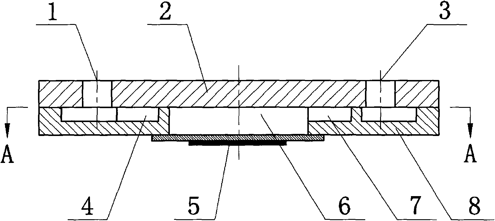
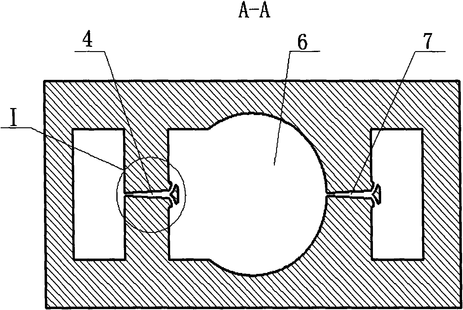
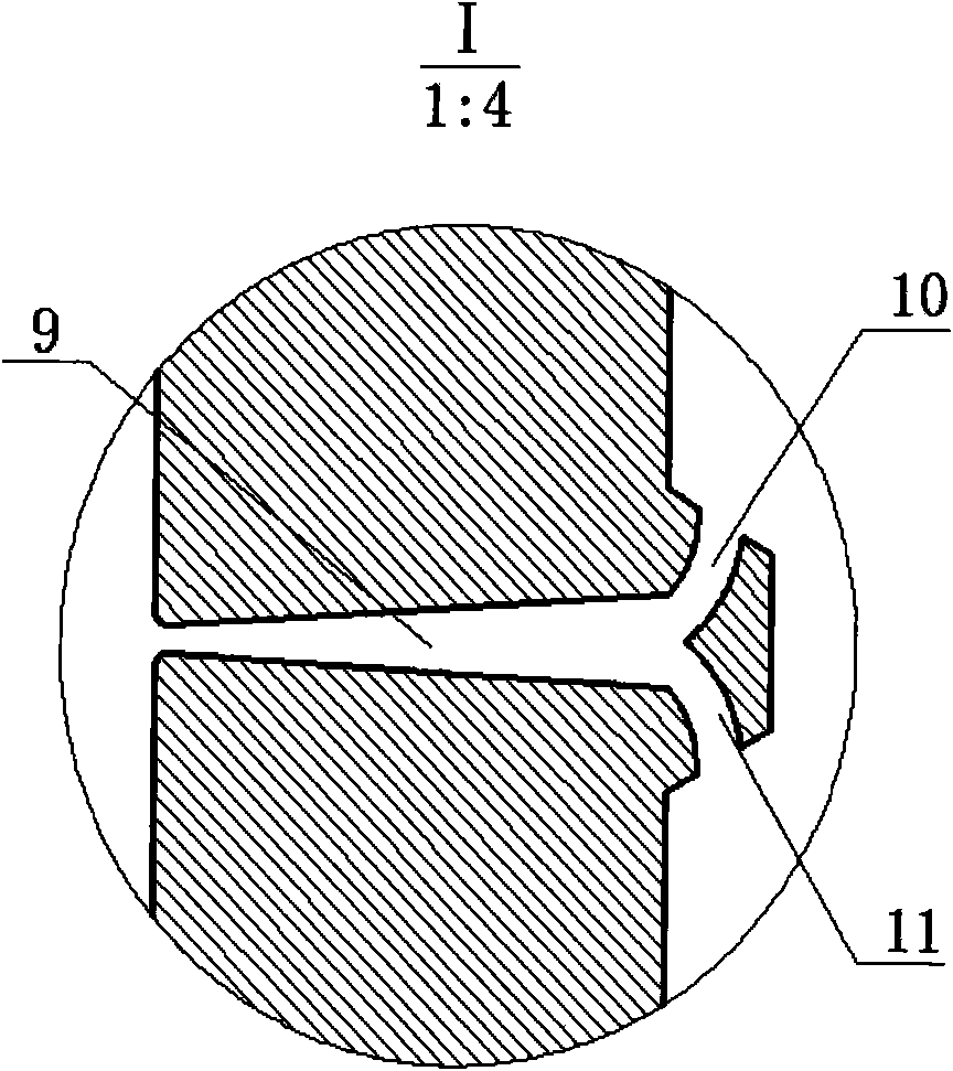
[0013] Such as Figure 1-3 , the present invention includes a pump body 8, a pump cover 2 and a piezoelectric vibrator 5, and the pump body 8 and the pump cover 2 are electrostatically bonded together. The piezoelectric vibrator 5 is fixed at the center of the lower part of the pump body 8 by an adhesive, and the pump inlet 1 and the pump outlet 3 are processed on the pump cover 2, and the pump inlet 1 and the pump outlet 3 are externally connected with an inlet pipe and an outlet pipe respectively. Two inlet flow tubes 4, outlet flow tubes 7 and a pump cavity 6 of the same structure are processed on the pump body 8 by using MEMS processing technology, wherein the pump cavity 6 is located between the inlet flow tube 4 and the outlet flow tube 7, and the inlet flow tube The flow pipe 4 and the outlet flow pipe 7 communicate with the pump chamber 6 respectively, and the three communicate with each other. The two inlet flow tubes 4 and outlet flow tubes 7 of the same structure a...


PUM

PropertyMeasurementUnit
Tube chiefaaaaaaaaaa
Widthaaaaaaaaaa
Lengthaaaaaaaaaa

Abstract

The invention discloses a valve-free piezoelectric pump of a logarithmic spiral combined tube in the field of microfluid transmission and control, comprising a pump body, a pump cover and a piezoelectric vibrator, wherein the pump body is provided with an inlet flow pipe, an outlet flow pipe and a pump cavity; the inlet flow pipe and the outlet flow pipe have the same structure, are coaxially arranged, have the equal distance with the circle center of the pump cavity and comprise confluence taper tubes and two shunt logarithmic spiral tube communicated with the large ends of the confluence taper tubes respectively; the included angle of center lines of the two shunt logarithmic spiral tubes is 120 degrees; the center lines of the two shunt logarithmic spiral tube are symmetrical to the center lines of the confluence taper tubes; and the contour lines of the shunt logarithmic spiral tube are two adjacent logarithmic spiral lines with a wrap angle of 45 degrees, which are determined by the logarithmic spiral equation of rho=rho0*ek theta. The valve-free piezoelectric pump has small size and high flow resistance coefficient ratio; the flow vortex in the pump is extremely small and has no damage to the transported medium; compared with the valve-free piezoelectric with other structure, the unidirectional flow resistivity is reduced greatly, so that the energy consumption is low and the energy-saving effect is remarkable; and the valve pressure free electric pump has simple structure and controls the flow rate more easily.

Description

technical field [0001] The invention relates to the field of microfluid transmission and control and micromechanical technology, in particular to a valveless piezoelectric pump. Background technique [0002] Piezoelectric pump is a kind of mechanical micropump, which belongs to positive displacement pump. It is widely used in the fields of micro-transportation of drugs, cell separation, cooling of electronic products (such as CPU), micro-injection of fuel, chemical micro-analysis, transition control in pipeline flow, etc. At present, piezoelectric pumps are mainly divided into two types: valve piezoelectric pumps and valveless piezoelectric pumps. The valved piezoelectric pump has a complex structure, is difficult to process, and is not suitable for working at a high frequency. The valveless piezoelectric pump has a simple structure, is more suitable for miniaturization and miniaturization, can meet the working requirements at high frequency, overcomes the shortcomings of t...

Claims


Application Information

Patent Timeline
IPC IPC(8): F04B43/04F04B53/00
Inventor 何秀华王健
Owner JIANGSU UNIV
Why Eureka
Try Eureka