
Multi-path cable monitor

A monitor and monitoring probe technology, applied in the direction of burglar alarm mechanical start, etc., can solve the problems of wire cutting or damage, the temperature of the alarm is difficult to dissipate, the monitoring effect is discounted, etc., to achieve the effect of eliminating monitoring dead zones and flexible and diverse monitoring methods.

Inactive Publication Date: 2011-02-16
刘家发
View PDF5 Cites 2 Cited by
  • Summary
  • Abstract
  • Description
  • Claims
  • Application Information

AI Technical Summary

Problems solved by technology

[0007] 3. When the room temperature is 25 degrees, when the human body faces the probe window of the pyroelectric infrared detection alarm for longitudinal movement, that is to say, it slowly approaches the infrared detection window until the alarm is slowly turned off, and the infrared detection alarm often unresponsive
Although the temperature is only in the 20s, the infrared alarm installed on the window is exposed to sunlight, and the internal temperature of the alarm is difficult to dissipate. The detection chip is also affected by the high temperature inside the box.
[0009] 5. There are also human body pyrolysis infrared detection alarms installed on the courtyard wall. Due to the interference of ambient temperature, its monitoring effect will be greatly reduced, and it is easy to be cut or damaged by the lead wire.
It is said that there are many car theft incidents where car thieves use the alarm noise as a cover to successfully commit crimes. The false alarm noise has made car owners accustomed to it and numb their reactions.
It is precisely this kind of car alarm that does not distinguish between true and false, which leads to repeated false alarms, so that when there is a real theft and an alarm occurs, the car owners are too lazy to find out. Such a car alarm is useless

Method used


Image

  • Multi-path cable monitor
  • Multi-path cable monitor

Examples


Embodiment Construction

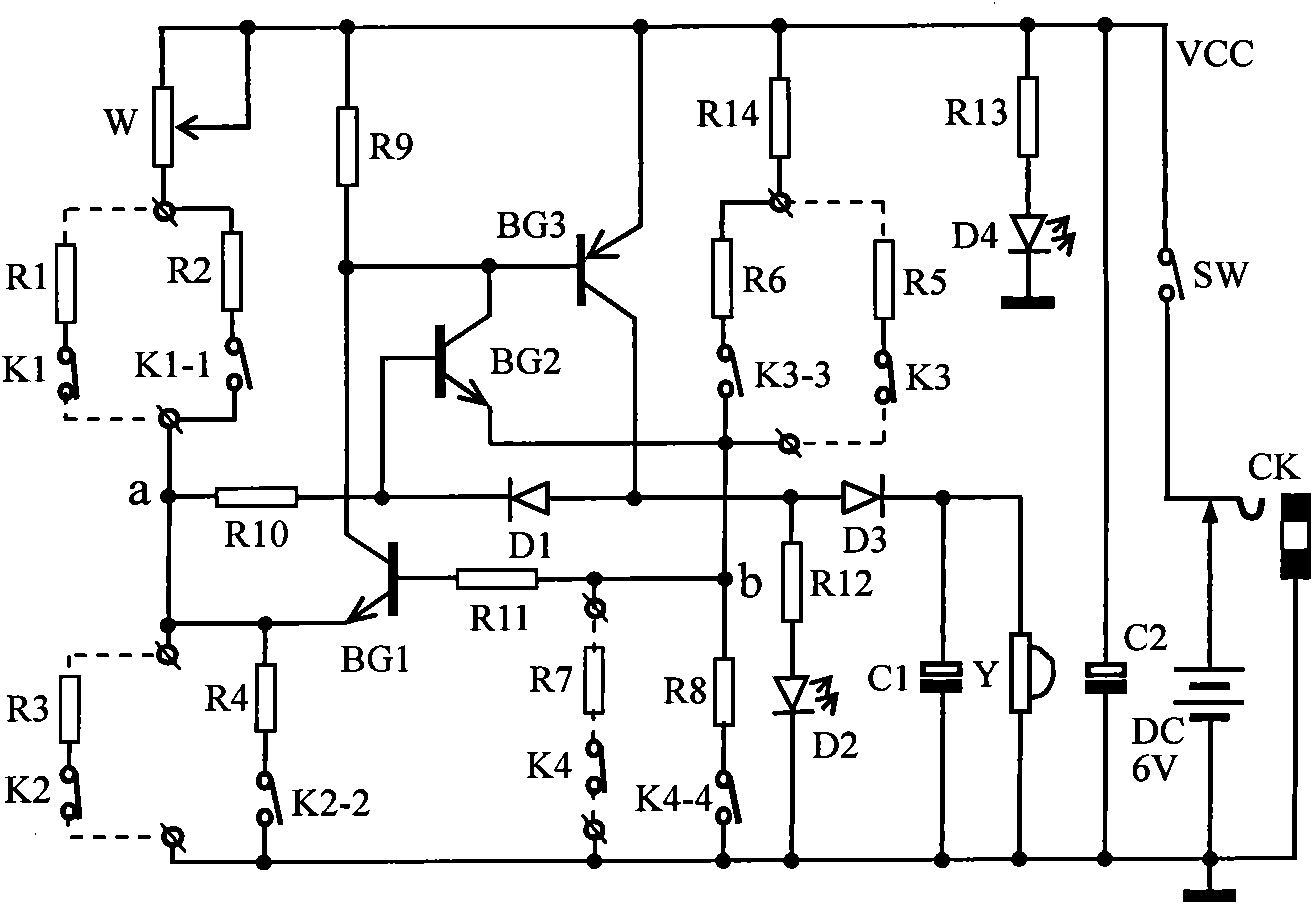
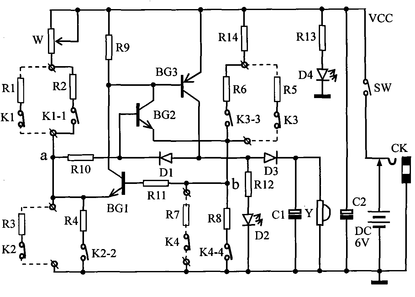
[0044] In the following, the relevant technologies and production points of the present invention will be further described in conjunction with the following embodiments according to the drawings and descriptions of the drawings.

[0045] Selection and production of components

[0046] 1. The selection of components should consider that the monitoring device must meet the requirements of long-term uninterrupted use, so strive to work stably and reliably, and select components with wide temperature adaptability and high temperature resistance.

[0047] 2. For component parameters, see component names and technical parameter tables.

[0048] Component names and main technical parameters

[0049] Component number

Component name

The main parameters

quantity

Remark

BG1, BG2

Silicon triode, 2SC9013

T0-92 plastic package

2

or 3DG6

BG3

Germanium transistor, 3AX31

or 3AX81

1

Domestic model

D1

Germanium ...


PUM


Abstract

The invention belongs to the technical fields of an electronic technology and a security protection monitoring technology, in particular to a multi-path cable monitor mainly used for detecting whether a human body enters a security area or whether a secured object is moved or not. The multi-path cable monitor comprises multi-paths of monitoring probes, a DC amplification and acousto-optic alarm circuit, a potential locking circuit, a power supply, a power supply filter circuit and a power supply indicator circuit and is characterized in that a bridge balance circuit is formed by two silicon transistors, four balance arms of a bridge circuit are substituted by four monitoring probes, and a microswitch in each probe is respectively connected in series with a resistor to form a balance arm of the bridge circuit. Once a certain monitoring probe is triggered or security lines are short-circuited or cut off, and the like, the monitoring device immediately alarms in an acousto-optic mode, and the circuit has no memory function so that the state of the bridge balance circuit is broken once an alarm signal is emitted, the potential locking circuit can automatically maintain the working state of the circuit, and an uninvited guest entering the security area can not singly clear the alarm signal.

Description

technical field [0001] The invention belongs to the technical field of electronics and security monitoring. A multi-channel wired monitor is a monitoring device mainly used to detect whether a human body enters a fortified area or whether a fortified object is moved. Background technique [0002] There are many types of monitoring and alarm devices on the market. The main ways to obtain alarm information are: one is the alarm made by the infrared sensor with the largest market share (using pyroelectric effect device plus Fresnel lens); The most representative ones are alarms made of anti-vibration, anti-prying, and anti-noise vibration displacement sensors; the third is a small number of alarms made of touch, induction probes, and microwave probes. Although the dominance and active role of these alarms in many fields of prevention cannot be questioned, they do have some problems in actual use. [0003] There is a problem [0004] (1) The human body pyrolysis infrared detec...

Claims


Application Information

Patent Timeline
IPC IPC(8): G08B13/02
Inventor 刘家发
Owner 刘家发
Learn More