Optical element, and light source unit and liquid crystal display device provided with the optical element

A technology of optical components and light source units, applied in the field of optical components, can solve the problems of low light extraction efficiency of light diffusion plate, low light utilization efficiency, and difficulty in fully eliminating uneven brightness of backlight, so as to eliminate uneven brightness and improve extraction efficiency Effect

Inactive Publication Date: 2011-02-16
SEKISUI CHEM CO LTD
View PDF6 Cites 9 Cited by
  • Summary
  • Abstract
  • Description
  • Claims
  • Application Information

AI Technical Summary

Problems solved by technology

Therefore, the light extraction efficiency of the light-diffusing plate using the light-diffusing material is low
Therefore, when only a light-diffusing plate using a light-diffusing material is placed on the backlight, although brightness unevenness can be eliminated, there is a problem that the utilization efficiency of light emitted from the backlight becomes low.
[0012] In addition, although the methods disclosed in Patent Documents 2 to 5 can eliminate unevenness in brightness of backlights having linear light sources arranged in parallel to each other, it is difficult to sufficiently eliminate unevenness in brightness of backlights in which point light sources are arranged in a matrix.
Specifically, although uneven brightness of the backlight in a predetermined direction can be eliminated, it is difficult to sufficiently eliminate uneven brightness of the backlight in a direction perpendicular to the predetermined direction.

Method used


Image

  • Optical element, and light source unit and liquid crystal display device provided with the optical element
  • Optical element, and light source unit and liquid crystal display device provided with the optical element
  • Optical element, and light source unit and liquid crystal display device provided with the optical element

Examples


Deformed example 1

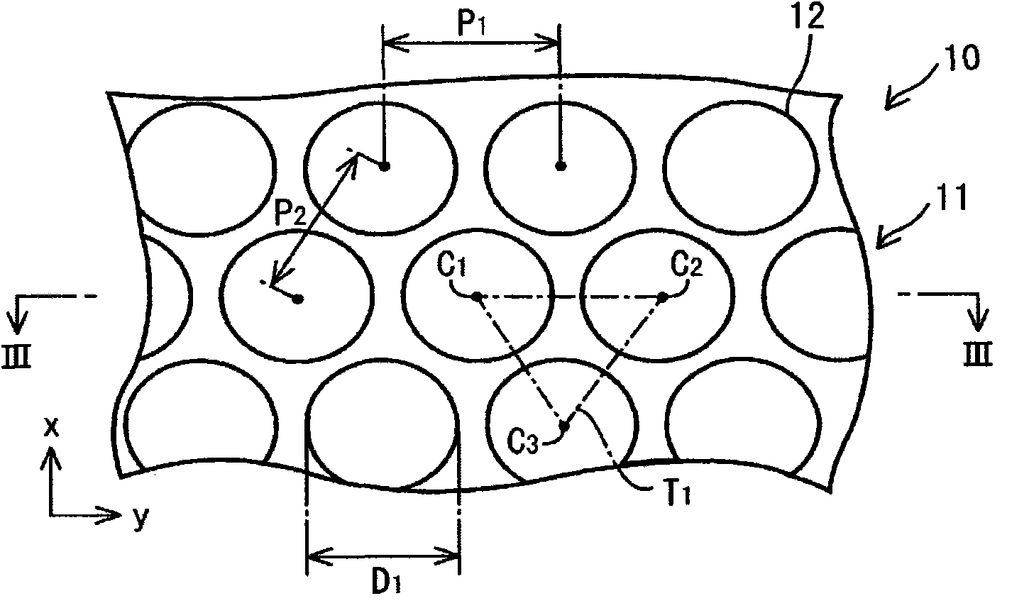
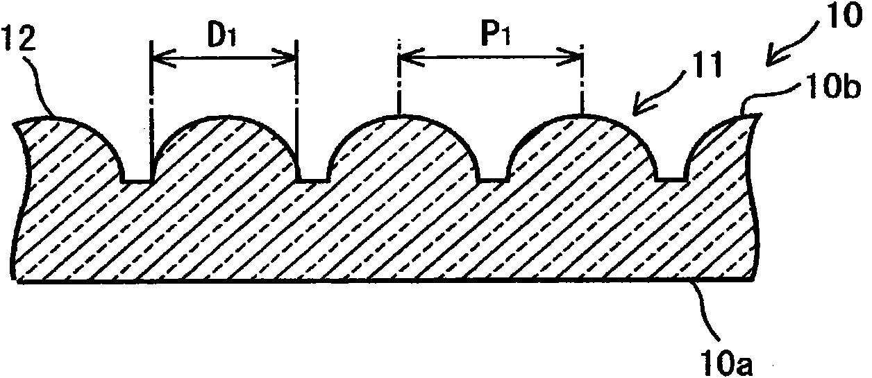
[0137] In the above-mentioned embodiment, the example in which the microlenses 22 are arranged in a so-called regular triangular lattice has been described. However, in the present invention, the arrangement of the microlenses 22 is not limited to a so-called regular triangle arrangement. Such as Figure 13 As shown, the microlenses 22 can also be arranged regularly and periodically in the mutually orthogonal x-direction and y-direction. Such as Figure 13 As shown, when the microlenses 22 are regularly and periodically arranged in the mutually orthogonal x-direction and y-direction, the pitches of the microlens array 21 can be approximately the same in the x-direction and y-direction. Therefore, the light diffusion performance of the optical plate 20 in the x direction and the light diffusion performance of the optical plate 20 in the y direction can be made substantially the same.

Deformed example 2

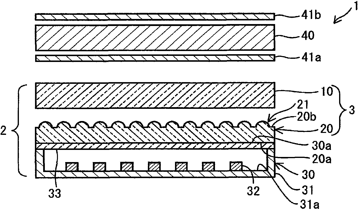
[0139] In the above implementation, an example in which the light source device 30 has a plurality of point light sources 32 has been described. However, in the present invention, the kind of light sources provided in the light source device 30 is not limited to point light sources. For example, Figures 14 to 15 As shown, for example, the light source device 30 may be a component having a plurality of linear light sources 34 arranged in parallel. The linear light source 34 is not particularly limited. For example, the linear light source 34 may be a cold cathode fluorescent lamp (Cold Cathode Fluorescent Lamp: CCFL) or the like.

Deformed example 3

[0141] In the above embodiment, the example in which the microlens array 21 having the plurality of convex microlenses 22 is formed on the light exit surface 20b of the optical plate 20 has been described. However, in the present invention, the microlens 22 may also have a concave shape. Furthermore, the microlens array 21 may also be formed on the light incident surface 20 a of the optical plate 20 . The microlens array 21 may be formed on both surfaces of the light exit surface 20 a and the light incident surface 20 a of the optical plate 20 .

[0142] Specifically, as Figure 16 As shown, for example, a microlens array 21 having a plurality of microlenses 25 formed in a concave shape may be formed on the light incident surface 20 a of the optical plate 20 .

[0143] (Other modifications)

[0144] At least one of a plurality of optical plates 20 and light diffusion plates 10 may also be arranged. That is, the number of objects to arrange each of the optical plate 20 and ...


PUM


Abstract

Provided is an optical element which has high light extracting efficiency and eliminates luminance nonuniformity in two orthogonally intersecting directions in backlight wherein dot-like light sources are arranged in matrix. An optical element (3) is provided with a light transmitting optical sheet (20) and a light diffusing sheet (10). The optical sheet (20) has a light incoming surface (20a) and a light outgoing surface (20b). At least on the light incoming surface (20a) or the light outgoing surface (20b), a microlens array (21) wherein a plurality of microlenses (22), each of which is formed in a protruding shape or a recessed shape, are arranged at a pitch less than 10[mu]m in a cycle and in matrix is formed. The light diffusing sheet (10) is arranged on the side of the light outgoing surface (20b) of the optical sheet (20). The light diffusing sheet (10) diffuses incoming light by refracting the incoming light.

Description

technical field [0001] The present invention relates to an optical element, a light source unit including the optical element, and a liquid crystal display device. Background technique [0002] Conventionally, a so-called direct type backlight has been known. In the direct type backlight, a plurality of light sources are arranged below the light emitting surface. Therefore, in the light exit surface of the backlight, the luminance directly above the light source tends to be higher than other portions. That is, the so-called lamp image may be easily recognized visually. [0003] Conventionally, various methods for eliminating brightness unevenness have been proposed in Patent Documents 1 to 5 and the like. For example, Patent Document 1 discloses a method of arranging a light-diffusing plate using a light-diffusing material on a light source. [0004] Furthermore, Patent Document 6 discloses an optical plate having a microlens array in which the diameter of the microlens ...

Claims


Application Information

Patent Timeline
Patent Type & Authority Applications(China)
IPC IPC(8): F21S2/00G02F1/13357G02B5/02G02B3/00
CPCG02F1/133604G02F1/133611G02F1/133603G02B3/0056G02F2001/133607G02F1/133607G02F1/133526
Inventor 林秀树菱田诚
Owner SEKISUI CHEM CO LTD
Why Eureka
Try Eureka