
Solar photoelectric complementary road de-icing and snow melting control system

A control system, solar photovoltaic technology, applied in the direction of roads, roads, light radiation generators, etc., can solve the problems of consuming a lot of manpower, material resources and financial resources, can not guarantee the safety of staff, pedestrians and driving hazards, etc., to improve road safety safety, reduce traffic accidents, and reduce operating costs

Inactive Publication Date: 2011-02-23
BAODING VICTORY TRAFFIC FACILITIES ENG CO LTD
View PDF4 Cites 12 Cited by
  • Summary
  • Abstract
  • Description
  • Claims
  • Application Information

AI Technical Summary

Problems solved by technology

At present, the main method for deicing and melting roads is to take treatment measures when there is ice and snow accumulation on the road. One of the treatment measures is to treat ice and snow by spreading salt or chemicals, and the other is to use machinery for ice and snow treatment. Those kinds of treatment measures need to consume a lot of manpower, material resources and financial resources, which not only easily pollute the environment, but also inevitably greatly increase the cost.
In addition, these treatment measures are only used when the snow accumulates to a certain thickness or freezes, which makes it impossible to survey the road conditions, so the safety of the staff cannot be guaranteed.
[0003] Since these measures are usually taken during the day, the biggest and most difficult problem is that the phenomenon of "freezing at night and turning into daytime" often occurs on the road, which will make the road surface smoother and the vehicles can hardly move. Exercising is also the most harmful situation for pedestrians and vehicles

Method used


Image

  • Solar photoelectric complementary road de-icing and snow melting control system
  • Solar photoelectric complementary road de-icing and snow melting control system
  • Solar photoelectric complementary road de-icing and snow melting control system

Examples


Embodiment Construction

[0021] The present invention will be described in further detail below in conjunction with the accompanying drawings.

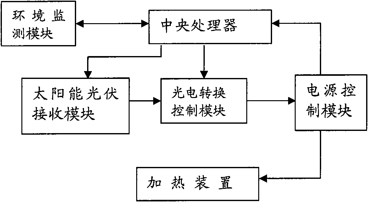
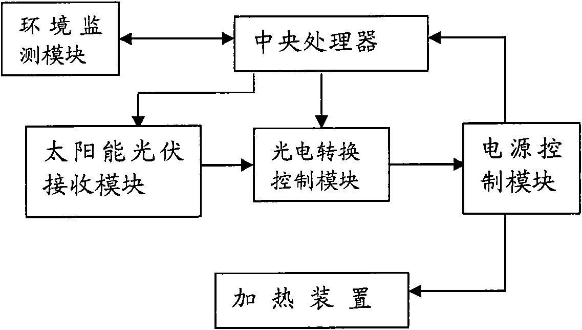
[0022] figure 1 It is a solar photoelectric complementary road deicing and snow melting control system, including a central processing unit, a solar photovoltaic receiving module, a photoelectric conversion control module, an environment monitoring module, a power supply control module and a heating device. The solar photovoltaic receiving module is connected with the power control module through the photoelectric conversion control module, the output terminal of the power control module is connected with the input terminal of the heating device, and the central processing unit is connected with the solar photovoltaic receiving module, photoelectric conversion control module, environmental monitoring module and heating device respectively. Connection via data bus.

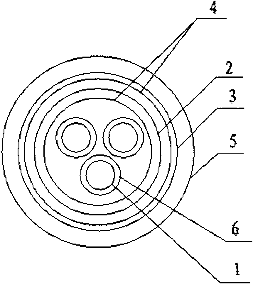
[0023] The cable-shaped heating device laid under the road surface includes an iron core 1 , ...


PUM


Abstract

The invention discloses a solar photoelectric complementary road de-icing and snow melting control system. The system comprises a central processing unit, a solar photovoltaic receiving module, a photoelectric conversion control module, an environmental monitoring module, a power control module and a heating device which is paved below a road surface, wherein the solar photovoltaic receiving module is connected with the power control module through the photoelectric conversion control module; the output end of the power control module is connected with the input end of the heating device; and the central processing unit is respectively connected with other modules through data buses. The system has the advantages of high heat efficiency, energy conservation, low operation cost and the like, can be controlled by a remote computer, automatically controls the work of the system according to practical situations of a road, adopts dual-energy setting of solar photovoltaic power generation and mains supply electrical energy, and can effectively prevent the road from icing and covering snow in a cold season, reduce traffic accidents and improve road safety.

Description

technical field [0001] The invention relates to a deicing and snow melting system for roads. Background technique [0002] With the change of the natural environment, the environmental impact caused by severe global weather has become more and more obvious in recent years, especially in winter, in areas with cold climate, ice and snow often appear, so it is necessary to ensure people's normal travel, road deicing and snow melting , especially the deicing and snow melting of highways is one of the essential projects. At present, the main method for deicing and melting roads is to take treatment measures when there is ice and snow accumulation on the road. One of the treatment measures is to treat ice and snow by spreading salt or chemicals, and the other is to use machinery for ice and snow treatment. Those treatment measures need to consume a lot of manpower, material resources and financial resources, which not only easily pollute the environment, but also inevitably great...

Claims


Application Information

Patent Timeline
IPC IPC(8): E01C11/26H02N6/00H05B3/56
Inventor 王士元王川王茜
Owner BAODING VICTORY TRAFFIC FACILITIES ENG CO LTD
Learn More