Multi-joint robot and system

A technology of robots and joint axes, which is applied in the direction of manipulators, mechanical equipment, program-controlled manipulators, etc., and can solve problems such as insufficient range of motion

Active Publication Date: 2011-02-23
YASKAWA DENKI KK
View PDF3 Cites 10 Cited by
  • Summary
  • Abstract
  • Description
  • Claims
  • Application Information

AI Technical Summary

Problems solved by technology

However, in the range of motion of the conventional robot manipulator, the winding work unique to the robot manipulator is within a narrow range of motion, so there are problems such as insufficient motion range, and it is necessary to arrange the workpiece slightly apart.

Method used


Image

  • Multi-joint robot and system
  • Multi-joint robot and system
  • Multi-joint robot and system

Examples


Embodiment 1

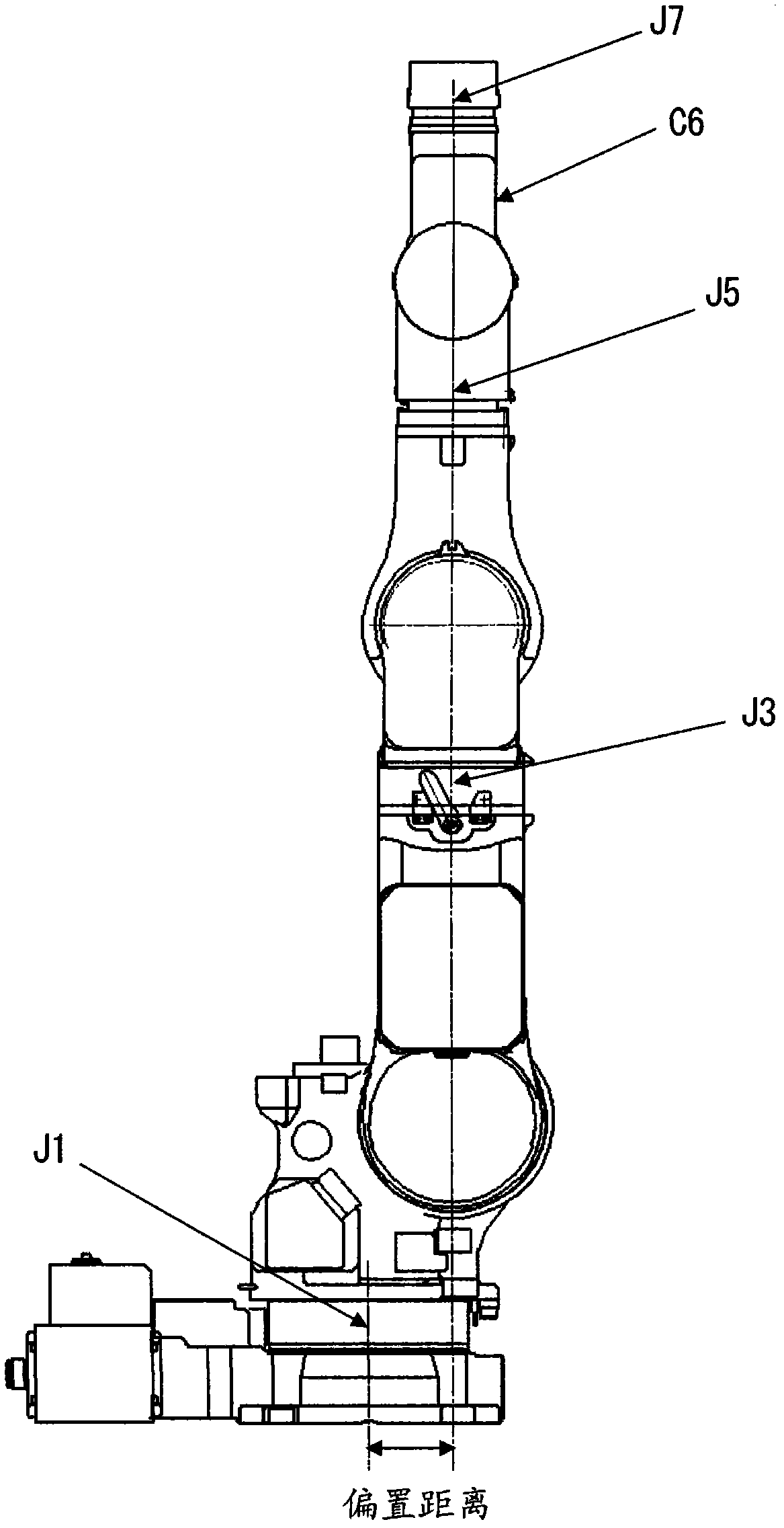
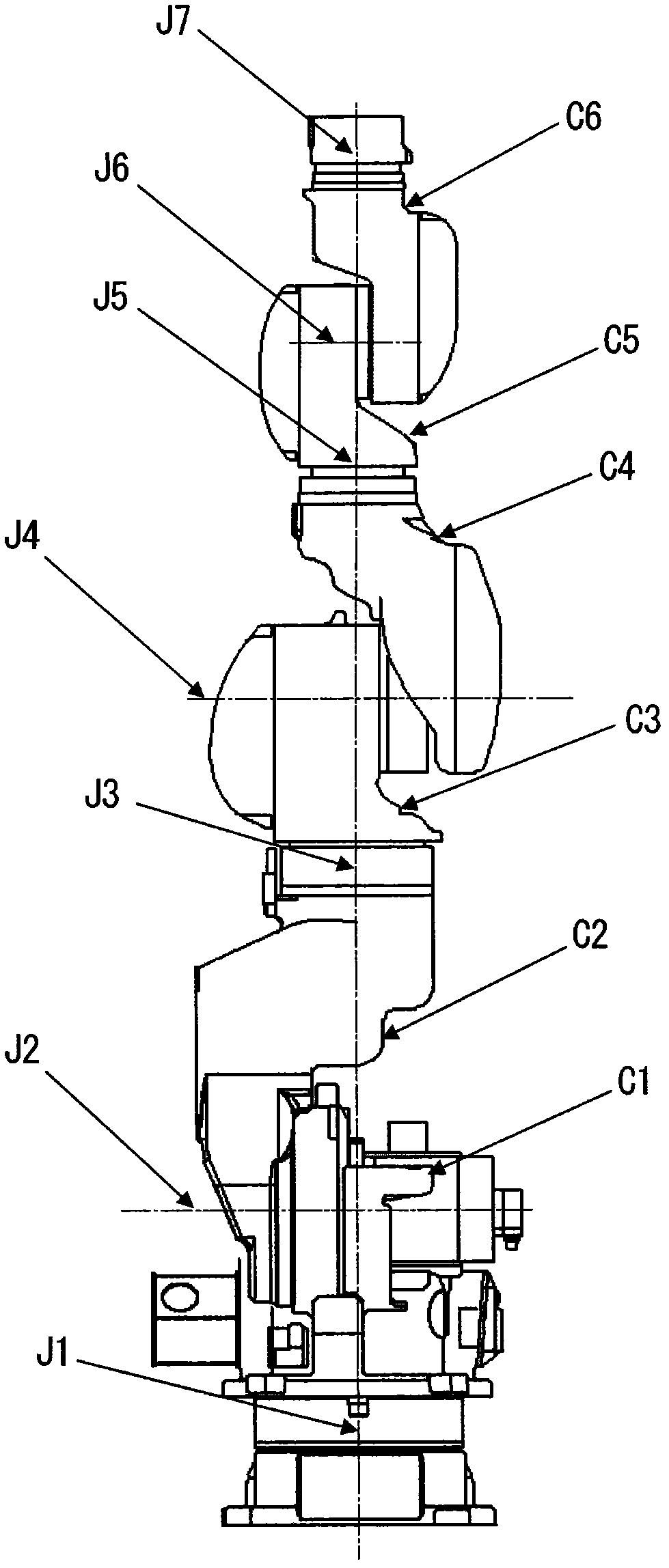
[0024] figure 1 is a side view of a robotic manipulator illustrating an embodiment of the present invention, figure 2 is its front view. The arm body C6 at the free end has a joint axis J7, and for example, a hand device having a force sensor, a spot welding device, and the like are attached to the joint axis J7.

[0025] The first arm body C1 rotates about a first joint axis J1 arranged vertically in the horizontal plane, and the second arm body C2 rotates about a second joint axis J2 arranged perpendicular to the first joint axis J1. The three-arm body C3 rotates around the third joint axis J3 arranged orthogonally to the second joint axis J2, and the fourth arm body C4 rotates around the fourth joint axis J4 arranged orthogonally to the third joint axis J3. The fifth arm body C5 rotates around the joint axis J5 arranged parallel to the fourth joint axis J4, and the sixth arm body C6 rotates around the joint axis J6 arranged orthogonally to the fifth joint axis J5. rotat...


PUM


Abstract

A robot manipulator and a system capable of maintaining an attitude having a higher degree of freedom by enlarging a main working area without changing the installation position of the manipulator. The robot manipulator (1) comprises a plurality of joint shafts. When the robot manipulator (1) is extended vertically in relative to the rotation center of the first joint shaft (J1) rotating in a horizontal plane, the rotation center of other joint shaft rotating in a horizontal plane is offset from the rotation center of the first joint shaft (J1). Consequently, the robot manipulator (1) can be disposed in a space nearer to an article.

Description

technical field [0001] The present invention relates to a manipulator and a system for performing spot welding in the conveyance or assembly of articles and in the manufacture of automobiles. Background technique [0002] The existing manipulator is a multi-joint manipulator, which has: a plurality of arms arranged in series; joints that connect two adjacent arms freely rotatable, and the inclination of the rotation axes of the adjacent joints an angle of 90 degrees; and at least one linear body disposed coaxially with the axis of rotation of the joint, the joint being composed of a servo motor and a reduction mechanism (for example, refer to Patent Document 1). [0003] Patent Document 1: Publication No. W02007 / 037131 [0004] Robot manipulators for product assembly and article transfer are often used in large-scale production line systems in which a plurality of robots are arranged to perform operations in a factory, and in cell production systems in which operations are...

Claims


Application Information

Patent Timeline
Patent Type & Authority Applications(China)
IPC IPC(8): B25J9/06
CPCB25J9/06B25J9/047Y10T74/20329Y10T74/20305
Inventor 伊藤雅人冈久学
Owner YASKAWA DENKI KK
Why Eureka
Try Eureka