Compartment structure for steam turbine
A steam turbine and engine room technology, applied in the direction of machines/engines, mechanical equipment, engine components, etc., can solve problems such as difficulty in maintaining machining accuracy, increasing building height, and inability to lift the upper part of the external engine room, so as to reduce bolts number, weight reduction, and improved operability
- Summary
- Abstract
- Description
- Claims
- Application Information
AI Technical Summary
Problems solved by technology
Method used
Image
Examples
Embodiment 1
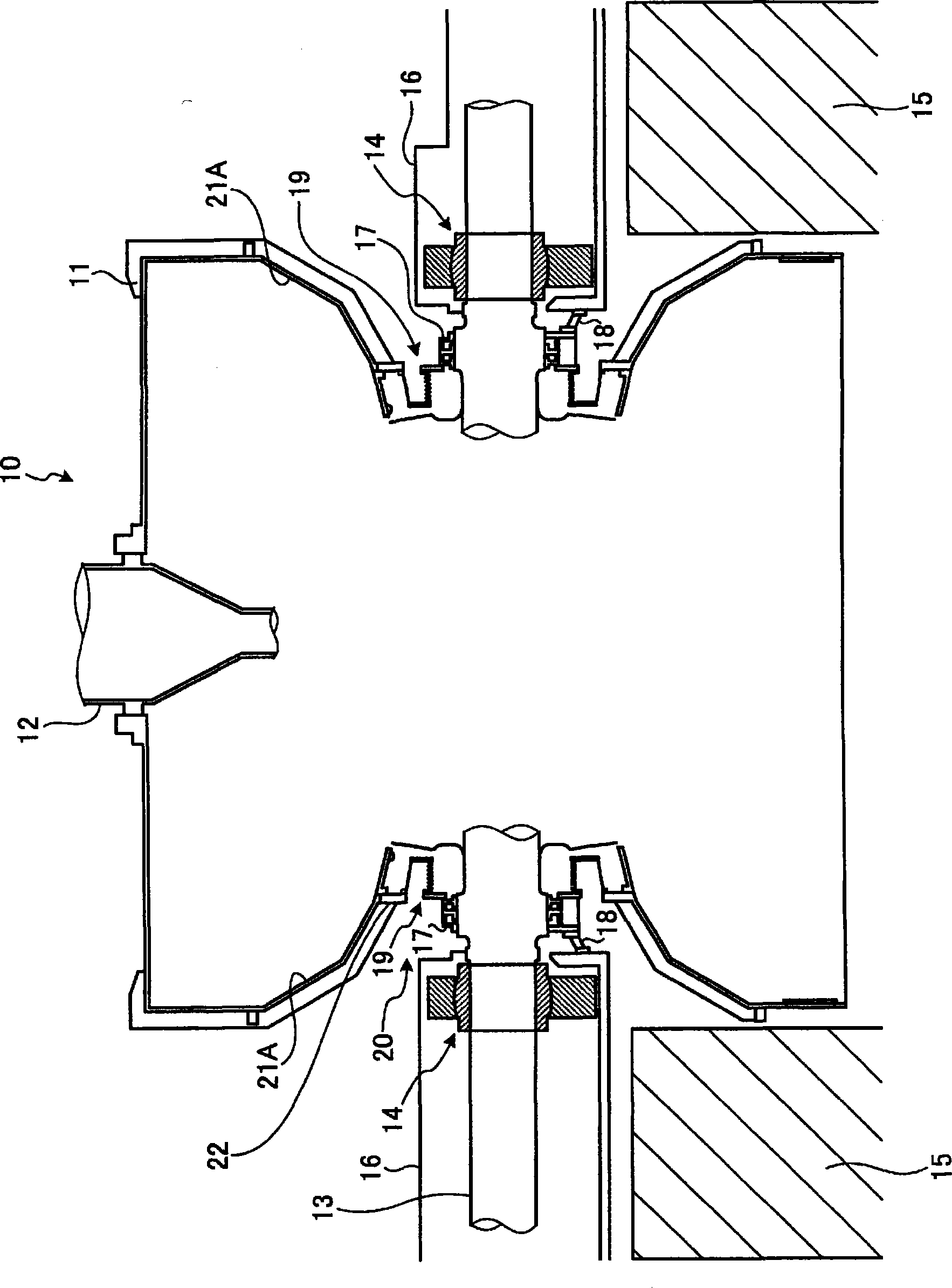
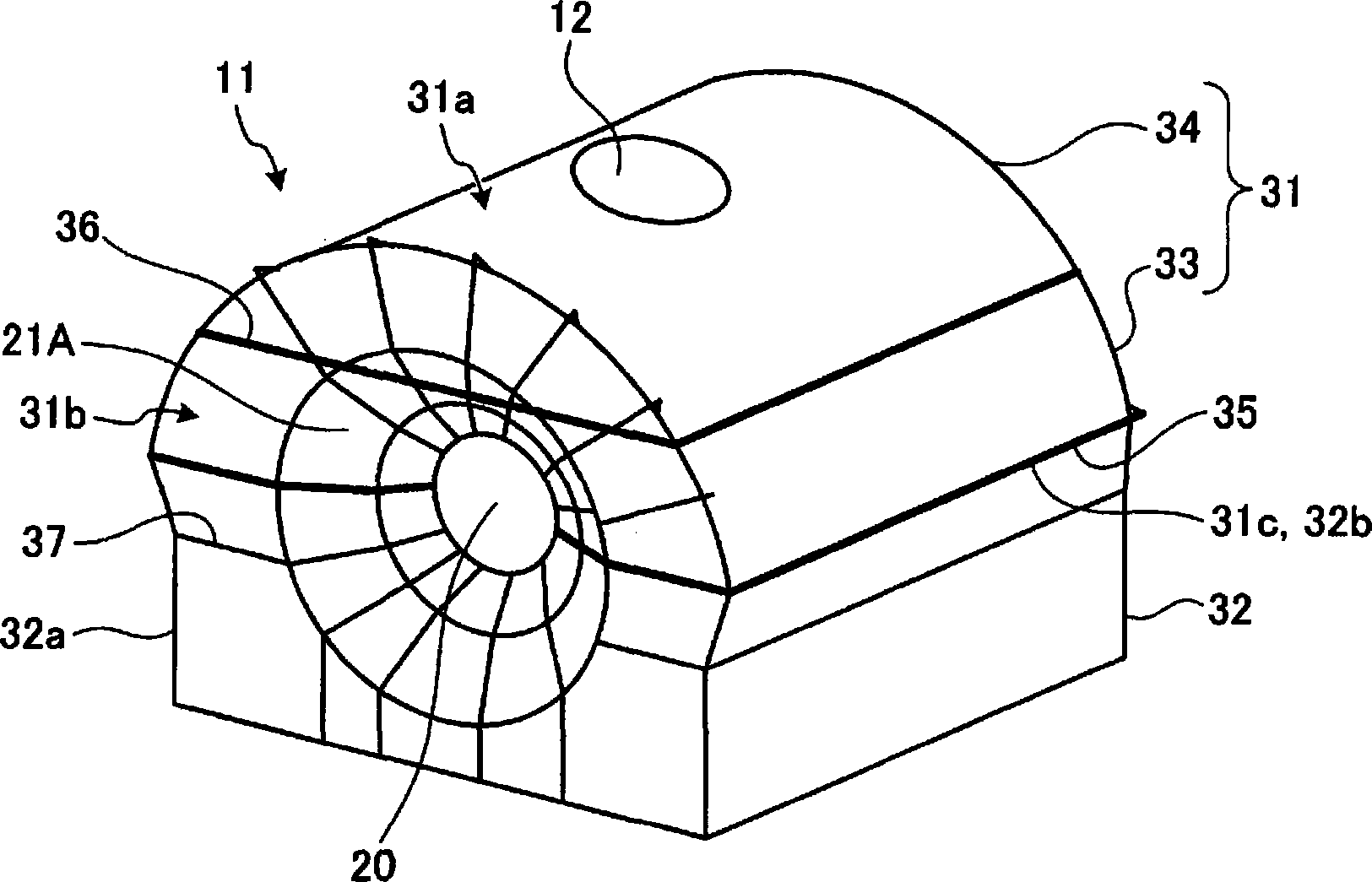
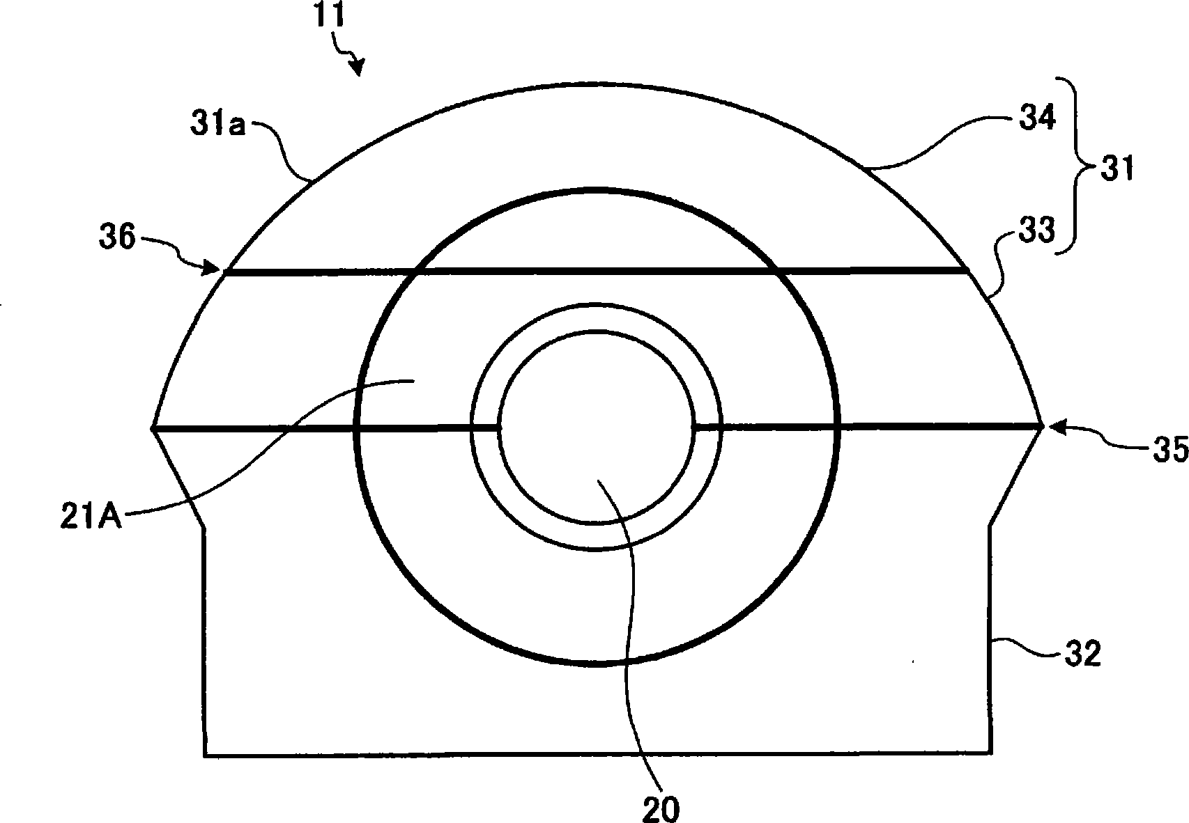
[0083] figure 1 It is a schematic configuration diagram of a steam turbine to which the machine room structure of the steam turbine according to Embodiment 1 of the present invention is applied. figure 2 It is a perspective view of an external machine room showing the machine room structure of the steam turbine according to Embodiment 1 of the present invention. image 3 It is a cross-sectional view showing the outer casing showing the casing structure of the steam turbine according to Embodiment 1 of the present invention, viewed from a direction perpendicular to the axial direction.
[0084] The steam turbine 10 of embodiment 1, such as figure 1 As shown, a steam inlet 12 is provided on the upper part of the external machine room 11, and a turbine rotor (hereinafter referred to as a rotor) 13 as a rotating body is supported by a bearing 14 rotatably supported. The bearing stand 16 on the foundation stand 15 made of concrete supports the bearing 14 . Furthermore, the glan...
Embodiment 2
[0097] Figure 4 It is a cross-sectional view showing the outer casing of the steam turbine casing structure according to Embodiment 2 of the present invention viewed from a direction perpendicular to the axial direction.
[0098] In addition, members having the same functions as those described in the above-mentioned embodiments are denoted by the same reference numerals, and repeated descriptions are omitted. In addition, the overall description of the steam turbine will be omitted, and only the configuration of the external machine room will be described.
[0099] In the machine room configuration of the steam turbine of this embodiment, such as Figure 4 As shown, the external machine room 11 is divided into an upper machine room (upper section) 41 having a top plate 31a and a lower machine room 42 having a through hole 20, and the lower machine room 42 is divided into a horizontal direction from the center of the through hole 20. an upper middle block 43 cut out to cont...
Embodiment 3
[0105] Figure 5 It is a cross-sectional view showing the outer casing showing the casing structure of the steam turbine according to Embodiment 3 of the present invention when viewed from a direction perpendicular to the axial direction. Figure 6 yes Figure 5 A-A cutaway view.
[0106] In addition, members having the same functions as those described in the above-mentioned embodiments are denoted by the same reference numerals and repeated descriptions are omitted. In addition, the overall description of the steam turbine will be omitted, and only the configuration of the external machine room will be described.
[0107] In the steam turbine chamber structure of the third embodiment, the end plate tapered portion 21A is further divided at the first dividing plane 35 that divides the outer machine room 11 into the upper machine room on the plane through which the rotor 13 passes. Room 51 and lower machine room 52.
[0108] That is, in the machine room structure of the stea...
PUM
 Abstract
Description
Claims
Application Information
 - R&D
- Intellectual Property
- Life Sciences
- Materials
- Tech Scout
- Unparalleled Data Quality
- Higher Quality Content
- 60% Fewer Hallucinations
Browse by: Latest US Patents, China's latest patents, Technical Efficacy Thesaurus, Application Domain, Technology Topic, Popular Technical Reports.
© 2025 PatSnap. All rights reserved.Legal|Privacy policy|Modern Slavery Act Transparency Statement|Sitemap|About US| Contact US: help@patsnap.com


