
Gas turbine control method and controller

By setting up a database and exploration control unit in the gas turbine, adjusting fuel and air flow, and predicting load changes, the problem of multi-frequency band combustion vibration is solved, the combustion stability and design state are maintained, and the operating efficiency and life of the gas turbine are improved. .

Active Publication Date: 2011-02-23
MITSUBISHI POWER LTD
View PDF9 Cites 15 Cited by
  • Summary
  • Abstract
  • Description
  • Claims
  • Application Information

AI Technical Summary

Problems solved by technology

However, as a result of such correction, if the horizontal axis represents the time and the vertical axis represents the load Figure 17 As shown, there is a basis Figure 15 When the automatic detection of the automatic detection causes an unexpected load increase or decrease, and the operation deviates from the ideal fuel flow rate and air flow rate assumed by the initial design value.

Method used


Image

  • Gas turbine control method and controller
  • Gas turbine control method and controller
  • Gas turbine control method and controller

Examples


Embodiment 1

[0049] First, using the Figure 12 , The sectional view used to explain the general composition of the burner is Figure 13 The gas turbine 2 will be briefly described. Should Figure 12 The gas turbine 2 shown has: a compressor 22 having an inlet guide vane 26; The combustion gas introduction pipe 38 supplies combustion gas to the turbine 24 and discharges the combustion gas to the outside through piping.

[0050] The rotation of the turbine 24 is transmitted to the compressor 22 through the rotary shaft 39, and the external intake air 25 is taken in from the intake port provided with a filter to generate compressed air, and the compressed air is supplied to the burner 23 from the compressed air introduction part 27 for combustion. For the inlet guide vane 26 provided in the compressor 22, the angle of the rotor vane 26 of the inlet guide vane 26, that is, the valve opening is controlled by the rotary vane on the air introduction side of the compressor 22, so that even if...

Embodiment 2

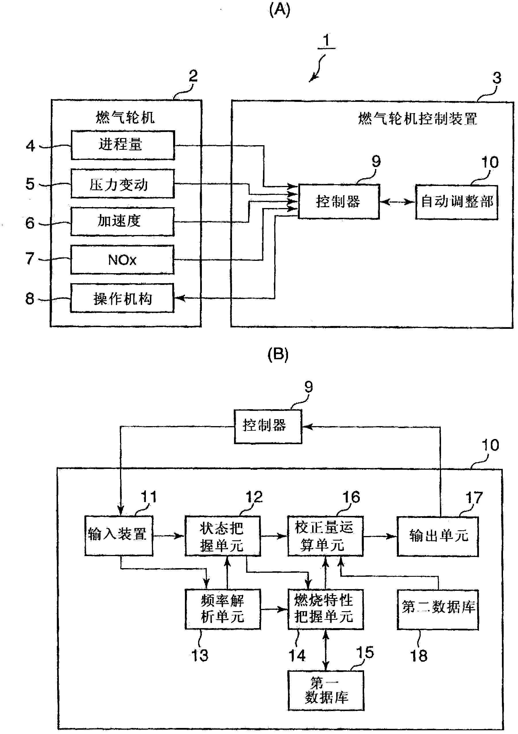
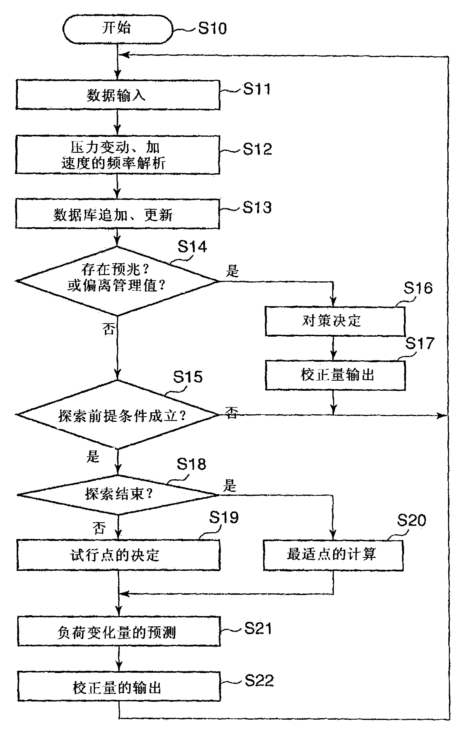
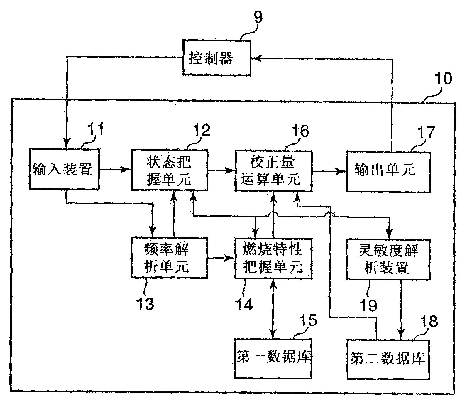
[0125] Next, use image 3 , Figure 4 , Figure 9 Example 2 of the present invention will be described. image 3 is to implement the gas turbine control method of the present invention figure 1 The block diagram of the device shown in (A), the detailed block diagram of the embodiment 2 of the automatic adjustment unit 9, Figure 4 is a flowchart of Embodiment 2 of the gas turbine control method of the present invention, Figure 9 This is an example of the configuration of the database used in Embodiment 2 of the present invention.

[0126] In the first embodiment described above, the load sensitivity data is collected by preliminaries such as trial operation, and the value obtained by this is stored in the second database 18 for use. However, in this method, it is necessary to manually calculate the sensitivity and store it, and since the content will not change unless the data is re-collected and rewritten, even if the performance of the compressor deteriorates or the f...


PUM


Abstract

Provided is gas turbine control method and controller whereby a design performance and an operating state based on ideal fuel flow rate and air flow rate assumed at the time of designing can be maintained by preventing an operation deviated from an operating state that is based on ideal fuel flow rate and air flow rate assumed by initial design values, in a gas turbine control method designed to search optimal operating conditions automatically using control inputs such as a pilot ratio. The gas turbine controller comprises a second database that stores load sensitivity, i.e. the correlation between the load amount of a gas turbine and control inputs such as a fuel flow rate, air flow rate, pilot fuel ratio, and top hat fuel ratio in the gas turbine, wherein the amount of load variation for at least one of control inputs, a fuel flow rate or an air flow rate supplied to a combustor is predicted according to operational conditions obtained by searching using the load sensitivity, regulation is made according to the prediction results, and the regulation results are stored in the second database.

Description

technical field [0001] The present invention relates to a gas turbine control method and device, and more particularly, to a gas turbine control method for operating without deviating from the ideal fuel flow rate and air flow rate assumed at the time of design by correcting for suppressing combustion vibration generated during gas turbine operation and devices. Background technique [0002] For example, in a gas turbine that drives a generator, the air flow rate and fuel flow rate to the combustor are finely adjusted during test operation based on the generator output, atmospheric temperature, humidity, etc., and are determined in advance, and these values ​​are used as initial design values run. However, the test run is only for a certain period of time, and it cannot be carried out based on all weather conditions. In addition, due to yearly changes such as compressor performance degradation and filter clogging, the actual air flow and fuel flow may differ from the design...

Claims


Application Information

Patent Timeline
Patent Type & Authority Applications(China)
IPC IPC(8): F02C9/54F02C9/28F02C9/34
CPCF05D2270/44F02C9/50F02C9/28F02C9/34
Inventor 野村真澄外山浩三
Owner MITSUBISHI POWER LTD
Learn More