Automatic clamping machine of denitration catalyst module

A denitrification catalyst and clamping technology, applied in the field of denitrification catalyst module automatic clamping machine, can solve the problems of high technical level requirements for workers, large module damage, high labor intensity, etc., and achieve fast action response, high operating efficiency and frictional resistance small effect

Active Publication Date: 2011-03-09
JIANGSU LONGYUAN CATALYST CO LTD
View PDF11 Cites 12 Cited by
  • Summary
  • Abstract
  • Description
  • Claims
  • Application Information

AI Technical Summary

Problems solved by technology

This manual operation method has high labor intensity, poor stability, great damage to the module, and requires high technical level of workers.

Method used


Image

  • Automatic clamping machine of denitration catalyst module
  • Automatic clamping machine of denitration catalyst module

Examples


Embodiment Construction

[0010] The specific embodiments of the present invention will be further described below in conjunction with the accompanying drawings.

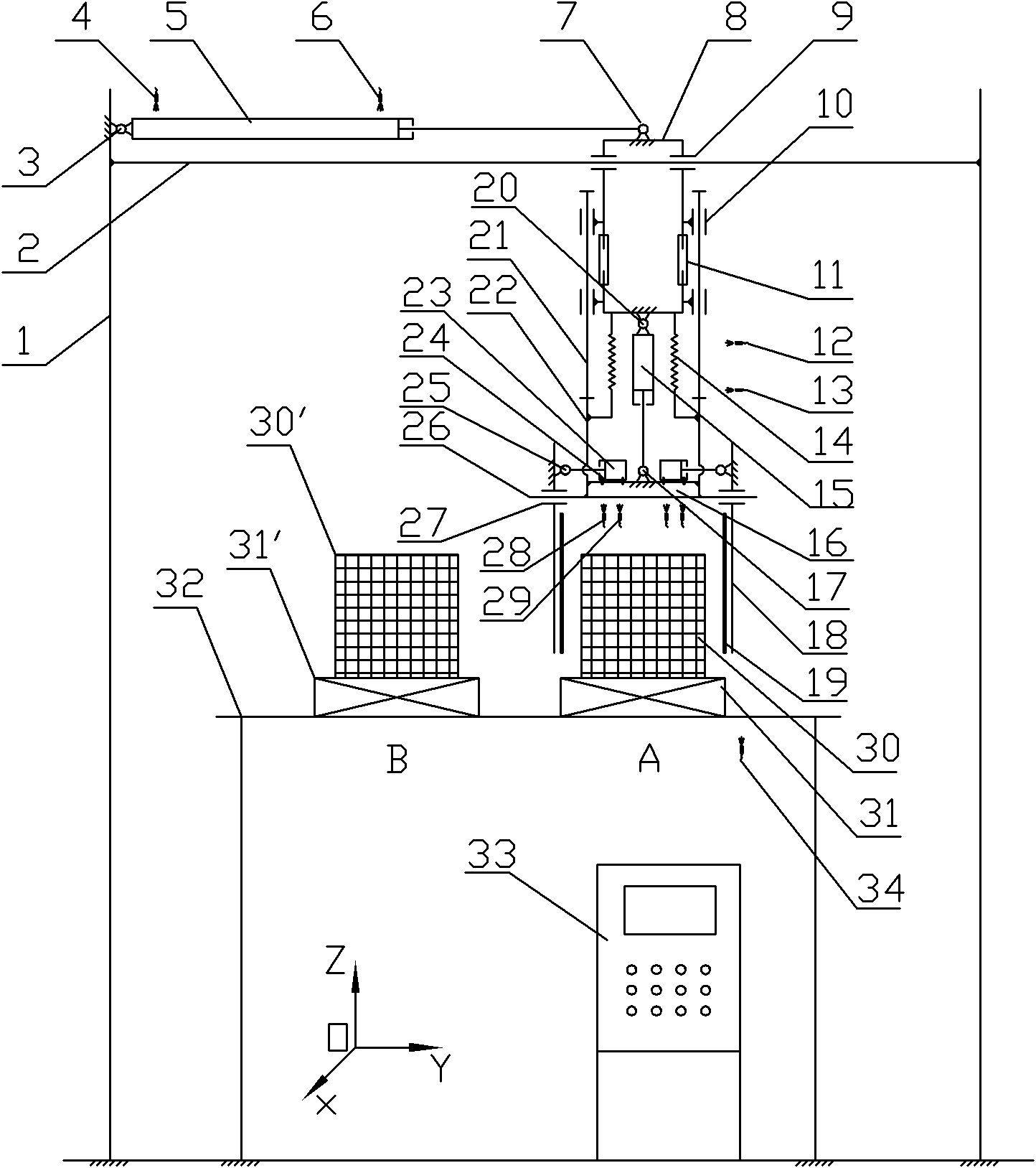
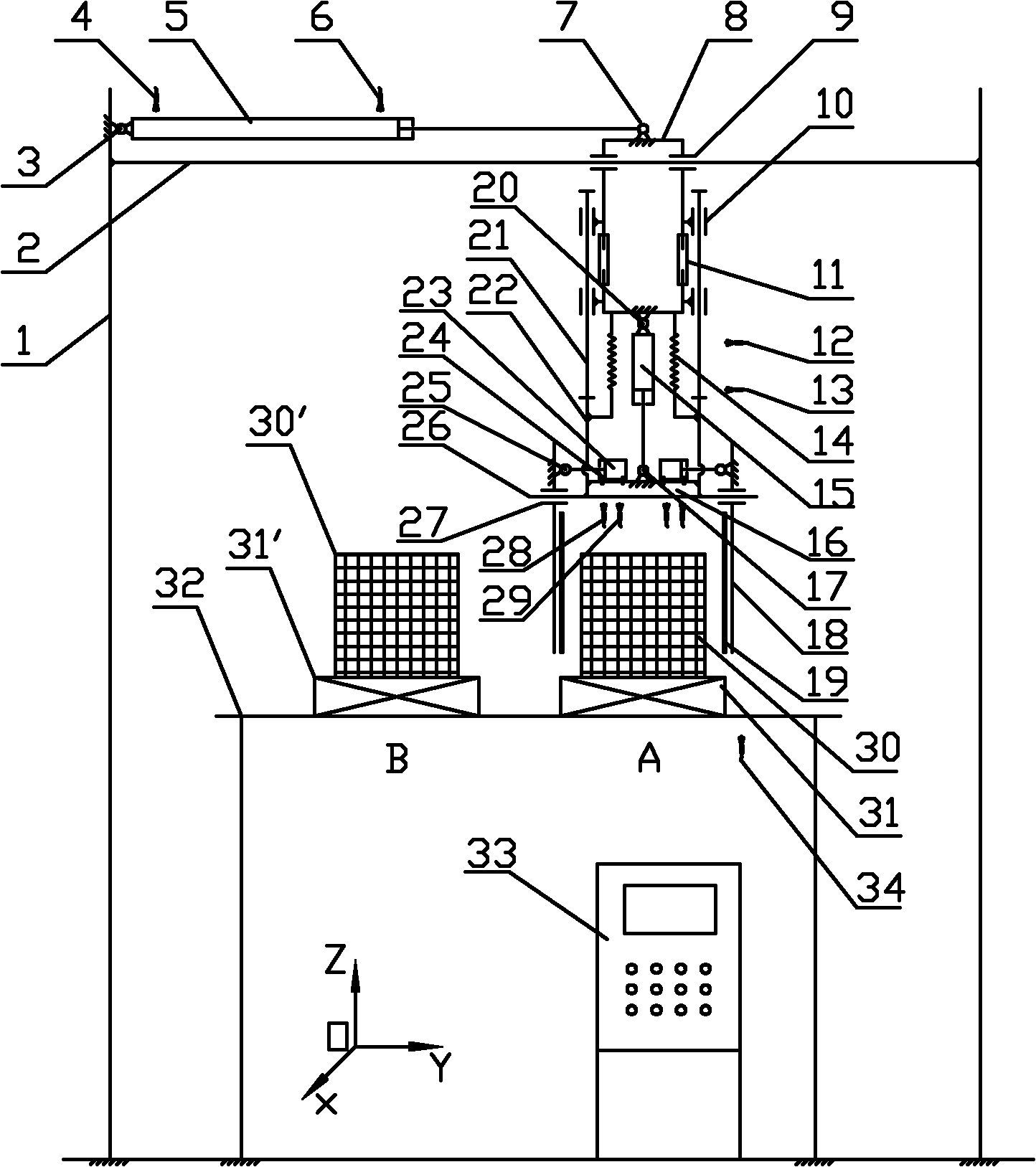
[0011] figure 1 Among them, including clamping machine frame column 1, clamping machine beam horizontal sliding guide rod 2, horizontal moving cylinder bottom twist support 3, horizontal cylinder retraction position electromagnetic induction switch 4, horizontal displacement cylinder 5, horizontal cylinder push-out position electromagnetic induction Switch 6, horizontally moving cylinder head twisting support 7, moving portal frame 8, linear bearing 9, linear bearing 10, height adjustment bolt 11, electromagnetic induction switch 12 for lifting cylinder retraction position, electromagnetic induction switch 13 for lifting cylinder push-out position, balance Spring 14, lifting cylinder 15, clamping support 16, lifting cylinder head twisting support 17, splint 18, sponge 19, lifting cylinder bottom twisting support 20, lifting sliding guide rod...


PUM


Abstract

The invention relates to an automatic clamping machine of a denitration catalyst module, which is characterized in that a horizontal displacement cylinder is fixed on a frame strut of the clamping machine; a movable door-shaped frame is fixed on the horizontal displacement cylinder; the movable door-shaped frame is matched with a horizontal slide guide rod of a beam of the clamping machine in a slide mode; the bottom of the movable door-shaped frame is fixedly provided with a vertical lifting cylinder; a clamping support is fixed on a piston rod of the lifting cylinder; two clamping cylindersin the horizontal direction are arranged on the clamping support in a back-to-back mode; the piston rod of each clamping cylinder is fixedly provided with a vertical clamping plate; and an electromagnetic induction switch in the contraction position of the horizontal cylinder, an electromagnetic induction switch in the pushing-out position of the horizontal cylinder, an electromagnetic induction switch in the contraction position of the lifting cylinder, an electromagnetic induction switch in the pushing-out position of the lifting cylinder, an electromagnetic induction switch in the pushing-out position of the clamping cylinder and an electromagnetic induction switch in the contraction position of the clamping cylinder are respectively and electrically connected with a programmable logic controller (PLC) control tank of the clamping machine. The automatic clamping machine of the invention can adopt the PLC control and has the advantages of completely automatic displacement and high working efficiency.

Description

technical field [0001] The invention relates to the manufacturing equipment of the denitration catalyst module used in the selective catalytic reduction (SCR) technology, in particular to an automatic clamping machine for the denitration catalyst module. Background technique [0002] At present, the pollution of nitrogen oxides (NOx) continues to intensify, and the content greatly exceeds the standard. Photochemical smog pollution has even appeared in some areas of our country, which has seriously affected economic development and people's lives. Thermal power plants are the largest pollution source of NOx emissions, accounting for more than 36% of total emissions. Controlling nitrogen oxide emissions has become the third key pollution control task for thermal power plants after flue gas dust removal and desulfurization. With the promulgation of "Emission Standards of Air Pollutants for Thermal Power Plants" (GB13223-2003), Selective Catalytic Reduction (SCR) technology has ...

Claims


Application Information

Patent Timeline
IPC IPC(8): B01J37/00B01J35/04B01D53/90B01D53/56
Inventor 史大维白伟刘长松
Owner JIANGSU LONGYUAN CATALYST CO LTD
Why Eureka
Try Eureka