
Multi-functional transcranial magnetic stimulator

A transcranial magnetic stimulation, multi-functional technology, applied in the direction of equipment, magnetic therapy, scientific instruments, etc., can solve the problems of difficult software development, low cost, and the inability of the transcranial magnetic stimulator to independently and safely treat, and achieve the guaranteed Running speed and quality, full-featured effects

Inactive Publication Date: 2011-03-16
香港脑泰科技有限公司
View PDF3 Cites 15 Cited by
  • Summary
  • Abstract
  • Description
  • Claims
  • Application Information

AI Technical Summary

Problems solved by technology

[0005] At present, some of the known transcranial magnetic stimulators do not have myoelectric collection devices and need to be used together with known electromyography devices. Some of them do not have temperature measuring devices and cannot promptly remind doctors of overheated coils. Many problems make the transcranial magnetic stimulators unable to Independent and safe treatment; in addition, the known transcranial magnetic stimulator, its control part is basically embedded, it is characterized in that it does not need to use a special computer, small in size, low in cost and high in performance, but its software development is difficult , the technical difficulty used is high, and the basic requirements for software and hardware of programmers are very high, which is not conducive to users to use according to customization

Method used


Image

  • Multi-functional transcranial magnetic stimulator
  • Multi-functional transcranial magnetic stimulator
  • Multi-functional transcranial magnetic stimulator

Examples


Embodiment Construction

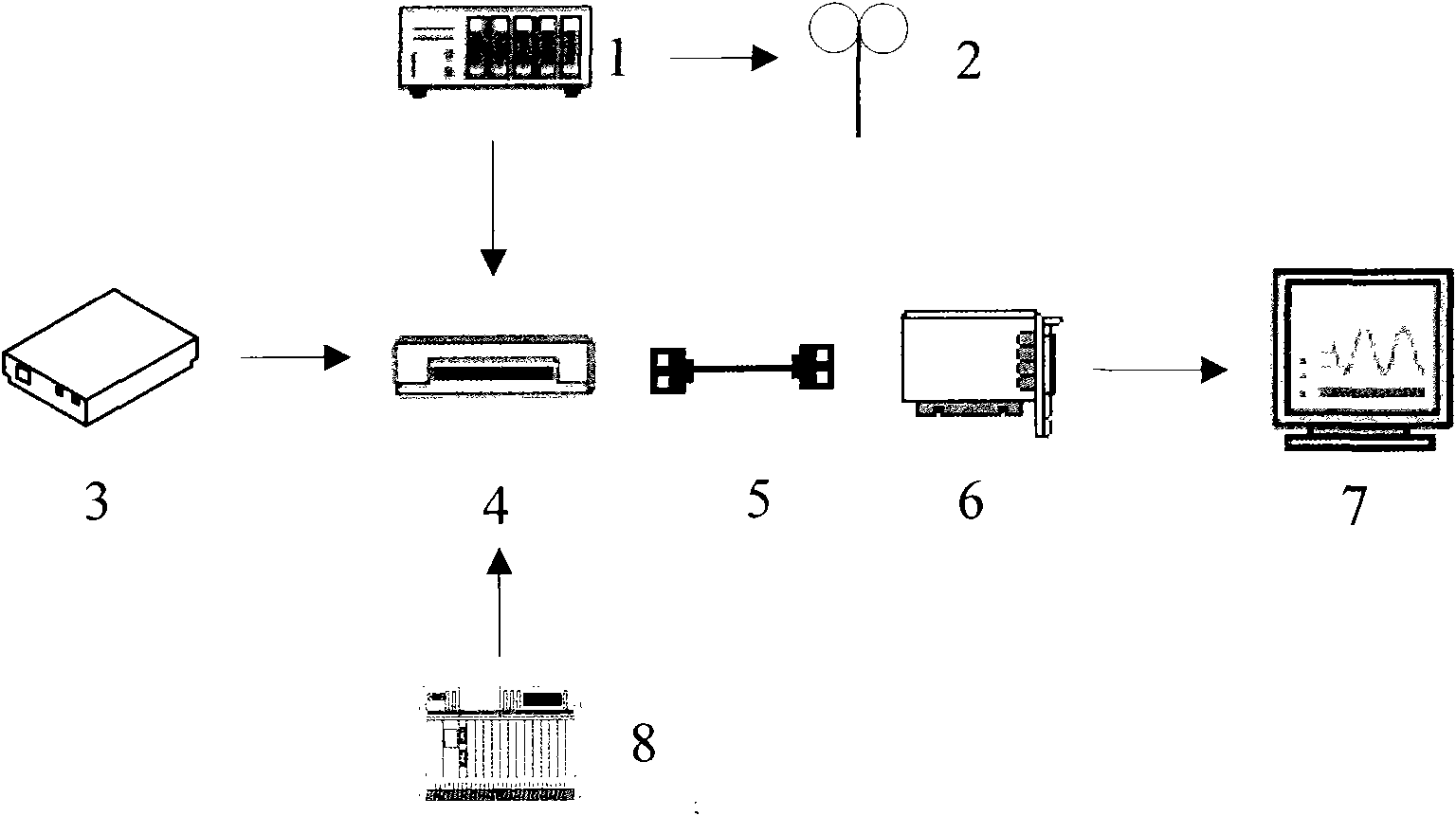
[0034] see figure 1 , the basic structure of the present invention is:

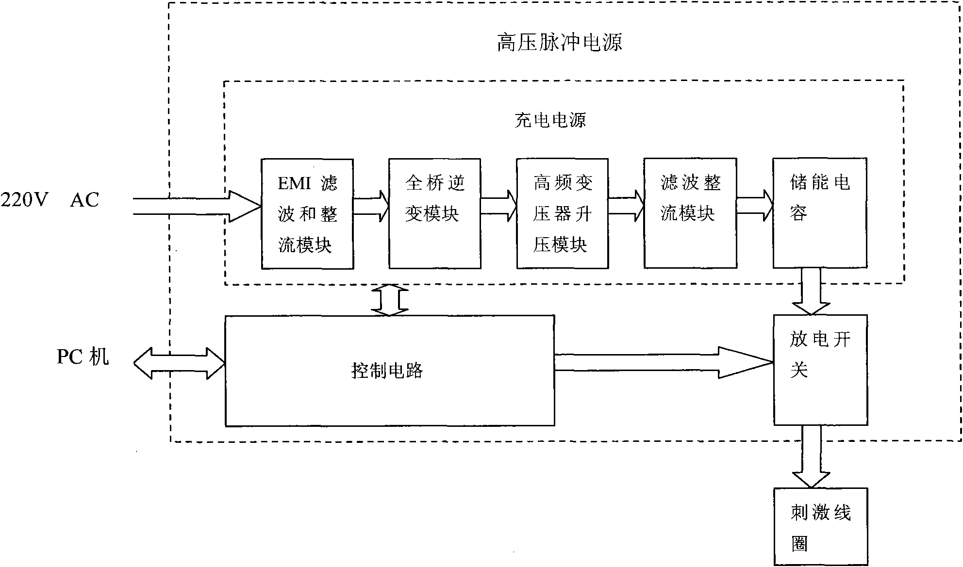
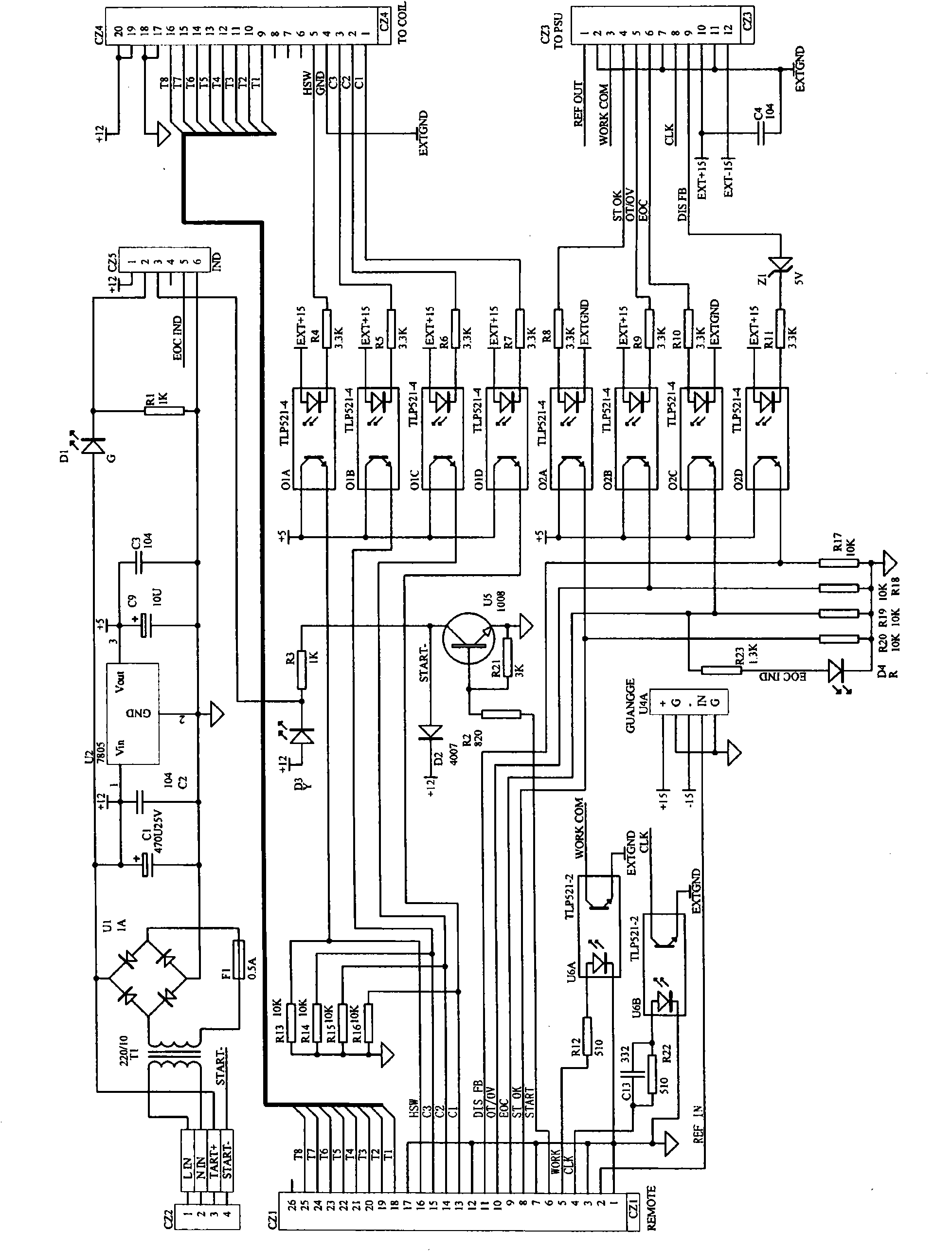
[0035] The high-voltage pulse power supply 1 is connected to the coil 2 through 14 control lines, the high-voltage pulse power supply 1, the myoelectric acquisition device 3 and the temperature measurement device 8 are respectively connected to the junction box 4 through data lines, and the junction box 4 is connected to the computer through the cable 5 The PCI data acquisition card 6 in the host computer is connected, and the PCI data acquisition card 6 communicates with the Labview software 7 to realize digital-to-analog conversion.

[0036] Junction box 4 among the present invention can not be used, and high-voltage pulse power supply 1, myoelectric acquisition device 3 and temperature measuring device 8 can be directly connected with PCI data acquisition card 6 by cables (data lines), and there are 24 data lines in total. It includes 12 high-voltage control lines, 2 temperature measurement lines, 2 m...


PUM


Abstract

The invention relates to a multi-functional transcranial magnetic stimulator. The multi-functional transcranial magnetic stimulator mainly comprises a high-voltage pulse power supply, a myoelectricity acquisition device and a temperature measurement device which are connected to a data acquisition card respectively, wherein the data acquisition card is connected to Labview control software of a microcomputer; and the high-voltage pulse power supply is connected with a stimulation coil. By the multi-functional transcranial magnetic stimulator, a high-voltage pulse generator is controlled to act on the coil through the labview software, so that various kinds of stimulation such as magnetic stimulation single pulse, repetitive pulse, random pulse and train pulse can be realized; the temperature measurement device is combined with the Labview software, so that the temperature of the coil can be acquired and alarm can be controlled; and the Labview software is combined with the myoelectricity acquisition device, so that myoelectricity signals can be acquired. In addition, the multi-functional transcranial magnetic stimulator also has multiple additional functions of database management, report printing, remote control, data communication and the like and can be widely used for diagnosis and treatment in psychiatry departments, neurology departments and laboratories.

Description

technical field [0001] The invention relates to a transcranial magnetic stimulation system, especially a transcranial magnetic stimulation system based only on a labview development platform. Background technique [0002] Transcranial Magnetic Stimulation (TMS) is a cortical stimulation method first created by Barker et al. in 1985. It has the advantages of painless, non-invasive, easy to operate, safe and reliable, and has been clinically applied soon. The so-called "transcranial" means that the magnetic signal can pass through the skull without attenuation to stimulate the cerebral cortex. In practical applications, it is not limited to the stimulation of the brain. Peripheral nerves and muscles can also be stimulated, so it can be simply called "magnetic stimulation". . [0003] Magnetic stimulation is a form of physical stimulation. It uses time-varying current to flow into the coil to generate a high-intensity time-varying pulsed magnetic field. The time-varying pulsed...

Claims


Application Information

Patent Timeline
IPC IPC(8): A61N2/04A61B5/0488G01K7/18
Inventor 夏伟杰许海田
Owner 香港脑泰科技有限公司
Learn More