PFC (power factor correction) control method with high input power factor and control circuit thereof

A technology of power factor and control method, which is applied in the field of high input power factor PFC control method and its control circuit, can solve the problems of small output voltage ripple, low precision, complicated method, etc., and reduce the output voltage ripple , easy to achieve, simple control circuit effect

Active Publication Date: 2011-03-16
SOUTH CHINA UNIV OF TECH
View PDF1 Cites 30 Cited by
  • Summary
  • Abstract
  • Description
  • Claims
  • Application Information

AI Technical Summary

Problems solved by technology

[0006] The purpose of the present invention is to provide a high input power factor PFC control method, using the principle of equal impulse area to obtain a variable duty cycle control sequence that can achieve high power factor, and solve the traditional PFC control method. The problem of complexity and low precision , while improving the power factor, it also obtains smaller output voltage ripple and higher efficiency

Method used


Image

  • PFC (power factor correction) control method with high input power factor and control circuit thereof
  • PFC (power factor correction) control method with high input power factor and control circuit thereof
  • PFC (power factor correction) control method with high input power factor and control circuit thereof

Examples


Embodiment Construction

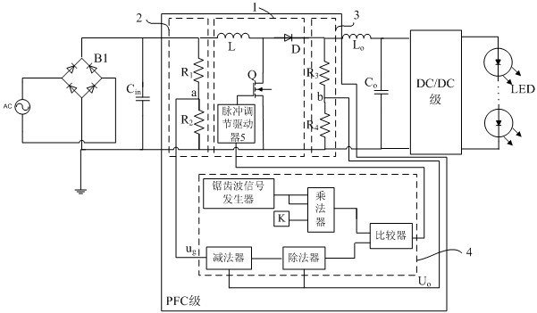
[0034] The following is an LED drive circuit with variable duty cycle control combined with PFC stage, as attached figure 1 , the specific implementation of the technical solution of the present invention will be further described in detail, but the implementation and protection scope of the present invention are not limited thereto.

[0035] The basic structure of the LED drive circuit is composed of input power supply, uncontrolled rectifier bridge, input filter, PFC stage, output filter, DC / DC stage, and LED lamp load.

[0036] Let the input voltage be , then the output voltage of the uncontrolled rectifier bridge is .

[0037] During one switching cycle, the peak value of the inductor current is:

[0038] (5)

[0039] in Indicates the switch conduction duty cycle.

[0040] From the equalization of volt-seconds across the inductor during each switching cycle:

[0041] (6)

[0042] in Indicates the duty cycle of the i...


PUM


Abstract

The invention provides a PFC (power factor correction) control method with high input power factor and a control circuit thereof. The method comprises the steps of controlling a switching tube to be switched on and switched off according to the principle of leading impulse area to be equivalent, and leading input inductive current and sinusoidal half-wave current to have the equivalent impulse area in each switching period, thereby realizing the high power factor (PF); furthermore, the higher the switching frequency, the closer to 1 the PF value is. In the control circuit, a circuit topological structure of a Boost converter and a control circuit for realizing a variable duty ratio sequence jointly constitute a PFC stage of a commonly used LED (light-emitting diode) driving power supply, the front stage of the PFC stage is connected with the output end of a non-controllable rectifier bridge of a single-phase diode via an input filter capacitor, the back stage of the PFC stage is connected with a DC/DC (direct current/direct current) stage of the commonly used LED driving power supply via an output filter inductor and an output filter capacitor. By adopting the PFC control method, not only the very high input power factor can be realized, but also output voltage ripple can be reduced; furthermore, the control circuit is simple and easy to realize an analog circuit, thereby being conductive to large-scale integration.

Description

technical field [0001] The invention relates to a single-phase power factor correction circuit in the field of switching power supplies, in particular to a PFC control method with high input power factor and a control circuit thereof. Background technique [0002] When the traditional AC-DC conversion circuit is running, the power factor of the grid side is generally around 0.6~0.7, and a large amount of harmonic current will be generated, which will cause serious harm to the grid. In order to meet the requirements of high power factor and suppression of harmonic generation, a PFC stage with power factor correction function is usually added. The PFC stage is a DC / DC switching converter added between the rectifier and the load. The voltage and current feedback technology is applied to make the waveform of the input current close to a sine wave to improve the power factor. According to the different requirements of different loads on the voltage, it is usually necessary to ad...

Claims


Application Information

Patent Timeline
Patent Type & Authority Applications(China)
IPC IPC(8): H02M1/42H02M1/14
CPCY02B70/126Y02B70/10
Inventor 张波张雪霁眭永明巢时斌张桂东肖文勋丘东元
Owner SOUTH CHINA UNIV OF TECH
Why Eureka
Try Eureka