Novel brake mechanism of rigid clutch press

A technology of rigid clutch and braking mechanism, which is applied in the field of forging machinery, can solve the problems of large energy consumption, low life, and large motor load, and achieve the effect of overcoming large motor load and noise

Inactive Publication Date: 2011-03-23
钱慧君
View PDF0 Cites 8 Cited by
  • Summary
  • Abstract
  • Description
  • Claims
  • Application Information

AI Technical Summary

Problems solved by technology

[0004] The object of the present invention is to: provide a kind of braking mechanism of novel rigid clutch press, the braking mechanism of this rigid clutch press can produce reasonable braking in the appropriate position in the whole working stroke of press crankshaft, namely this A braking mechanism of a rigid clutch press, in a complete working stroke of the crankshaft, only produces braking at the positions of the upper dead center and the

Method used


Image

  • Novel brake mechanism of rigid clutch press
  • Novel brake mechanism of rigid clutch press

Examples


Embodiment Construction

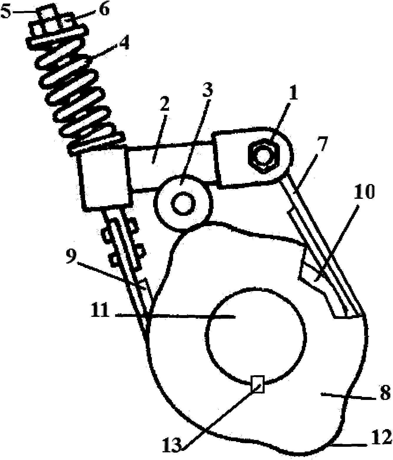
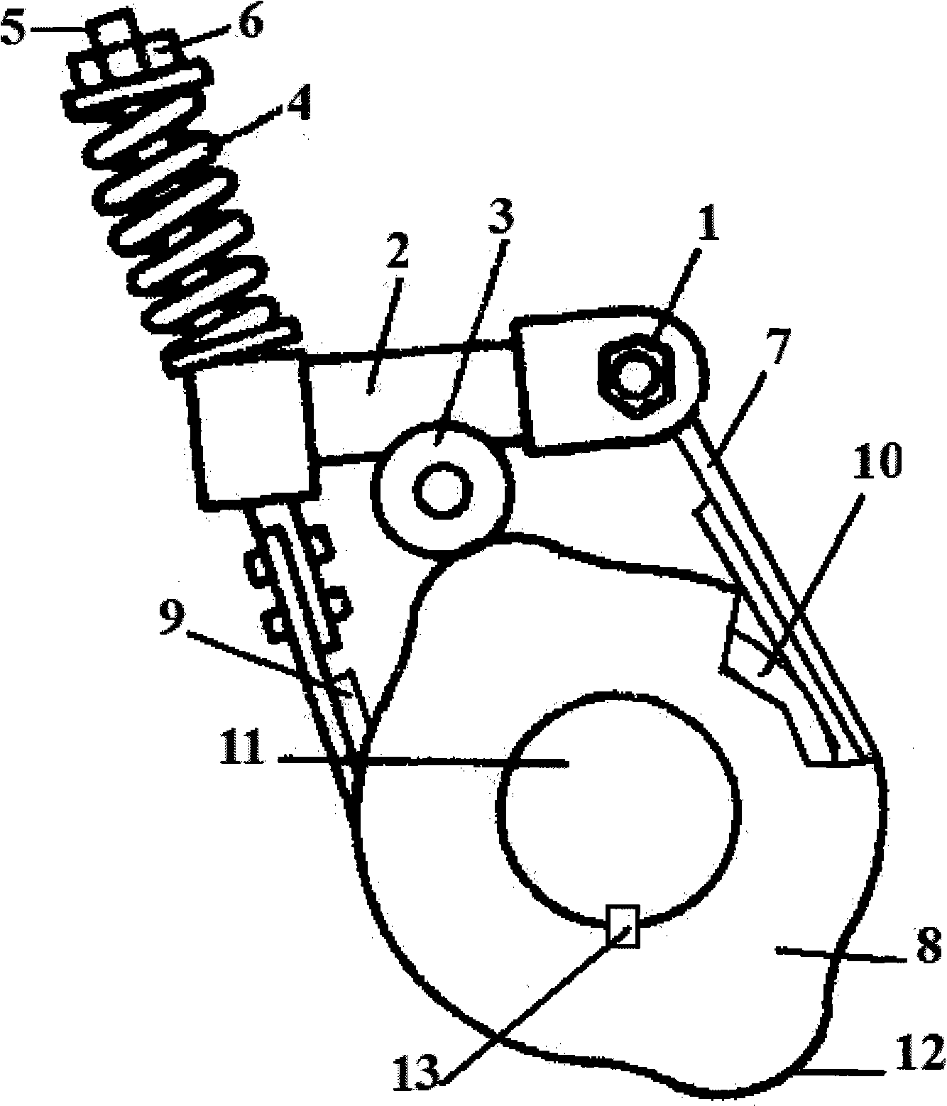
[0009] Install the brake wheel (10) and the cam (8) on the crankshaft (11) from the inside to the outside in turn, and fix them on the crankshaft (11) with the key (13). When installing, make the convex arc ( The position of 12) corresponds to the position of the top and bottom dead center of the crankshaft (11). Use the pin shaft (1) to install and fix the lever (2) on the top of the body. Make sure that the lever rotates flexibly around the pin shaft (1) during installation. ; Use the correct method to install and fix the roller (3) at the appropriate place in the middle of the lever (2), rivet the friction belt (9) on the brake belt (7), and fix the brake belt (7) One end is hinged with the pin (1), and the other end is fixed with the tension rod (5) in a proper way. Pass the tension rod (5) through the through hole on the lever (2) and put it on the body For the spring (4), use the nut (6) to properly compress the spring (4).


PUM


Abstract

The invention discloses a novel brake mechanism of a rigid clutch press. From inside to outside, a brake wheel and a cam are sequentially arranged and fixed on the upper surface of a crankshaft by a bolt in a way that the positions of protruding arcs correspond to the positions of upper and lower dead points of the crankshaft. A lever is fixedly arranged on the upper surface of a machine body by a pin shaft in a way that the lever is ensured to flexibly rotate about the pin shaft. A roller is fixedly arranged at a proper position on the middle part of the lever by an accurate method. A friction belt is riveted on the upper surface of a brake belt by a rivet. One end of the brake belt is hinged with the pin shaft, and the other end of the brake belt is fixed with a tensioning pull rod by a proper method. The tensioning pull rod passes through a through hole on a lever body, and is sleeved with a spring which is properly pressed by a nut.

Description

Technical field [0001] The invention relates to a rigid clutch brake mechanism, in particular to a brake mechanism of a novel rigid clutch press. It belongs to the technical field of forging machinery. Background technique [0002] In order to reduce the impact and vibration of the press during operation, as well as the adverse effects of impact and vibration on the operating safety and the service life of the press, at the same time, it is also for the press to stop the crankshaft accurately during a single operation. At the dead center position, a mechanical cam brake is designed and installed in the rigid clutch press. [0003] It is currently known that in the structure of the cam brake of a rigid clutch press, the cam is an Archimedes curve, or other forms of curves that vary in the circumferential direction of the cam. Regardless of the cam curve form, in a rotation cycle of the crankshaft, the brake always brakes the rotation movement of the crankshaft. In fact, in a work...

Claims


Application Information

Patent Timeline
IPC IPC(8): B30B15/10B21J9/20
Inventor 钱慧君
Owner 钱慧君
Why Eureka
Try Eureka