
Installation structure for dustproof net

A technology of dust-proof net and configuration area, which is applied in the layout of power unit cooling combined, mechanical equipment, engine cooling, etc., can solve the problems of restriction, complicated production of dust-proof net, and difficulty in loading and unloading of dust-proof net, etc. Achieve the effect of prolonging life, low production cost and excellent versatility

Active Publication Date: 2011-03-23
HITACHI CONSTR MASCH CO LTD
View PDF8 Cites 3 Cited by
  • Summary
  • Abstract
  • Description
  • Claims
  • Application Information

AI Technical Summary

Problems solved by technology

[0005] The first problem is that since the installation position of the protective net, that is, the dust-proof net is determined by the installation position of the heat exchanger, there is a concern that the dust-proof net is installed in the opening and closing of the maintenance cover due to the installation position of the heat exchanger. In the position where it becomes difficult to attach and detach the dust filter in progress
[0006] The second problem is that since the shape and size of the dust-proof net is determined by the shape and size of the sealing frame that holds the condenser, when the shape and size of the dust-proof net are to be increased, it is restricted by the sealing frame.
[0007] The third problem is that, for example, in a plurality of construction machines having engine compartments of the same size, when it is desired to install structures with different shapes and sizes of heat exchangers, there may be concerns about the difference in the shapes and sizes of the heat exchangers. It is necessary to install a dust filter of the shape and size corresponding to each heat exchanger
That is, it is necessary to produce various dust-proof nets for each of the corresponding construction machines, and there is a concern that the production of dust-proof nets will become complicated.

Method used


Image

  • Installation structure for dustproof net
  • Installation structure for dustproof net
  • Installation structure for dustproof net

Examples


Embodiment Construction

[0026] Hereinafter, embodiment of the arrangement structure of the dustproof net of this invention is demonstrated based on drawing.

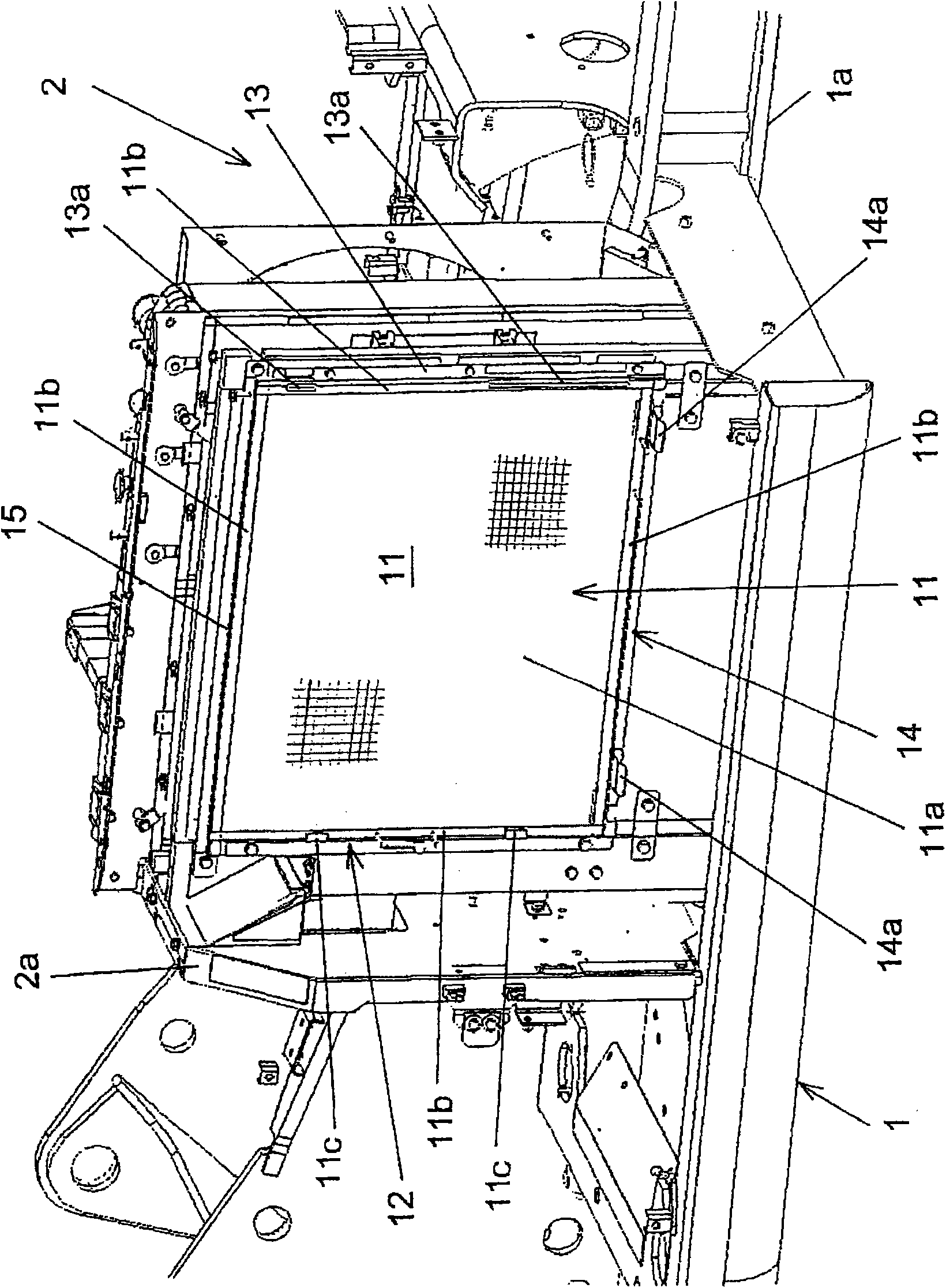
[0027] The arrangement structure of the dustproof net of this embodiment is equipped on a mechanical device such as a hydraulic excavator which is a construction machine. This hydraulic excavator has: a running body not shown in the figure; image 3 , Figure 6 and a front work machine (not shown) that is rotatably mounted on the swing body 1 in the vertical direction and performs excavation work of sand and soil. The revolving body 1 is provided with: an unillustrated driver's cab and a counterweight for ensuring weight balance; figure 1 , 2 Engine compartment 2 as shown.

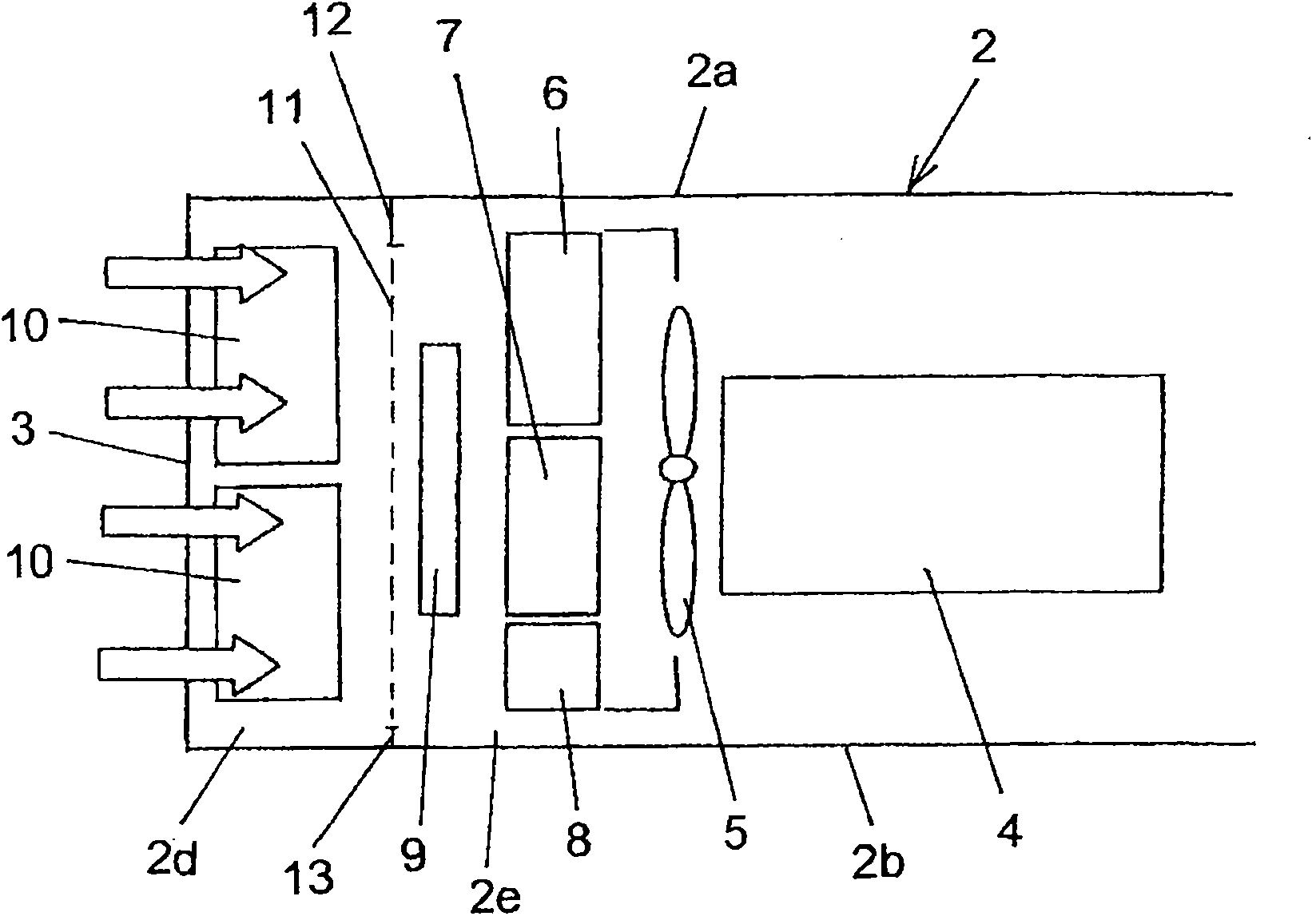
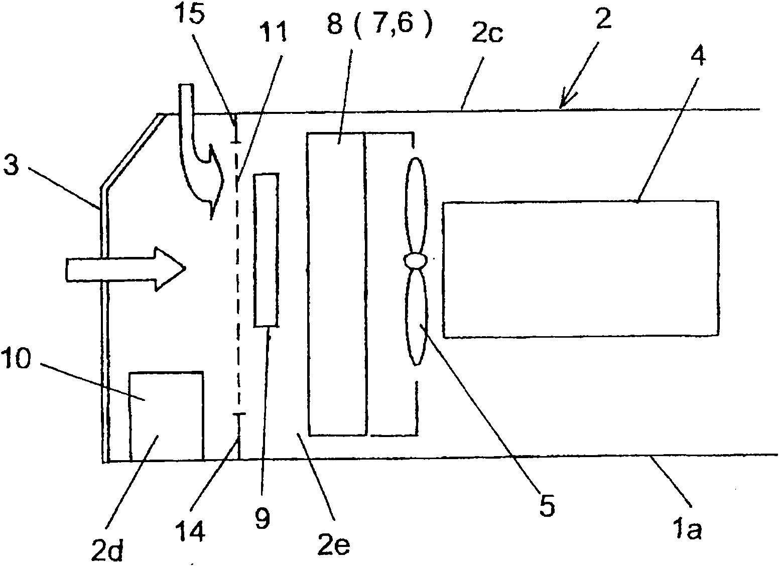
[0028] as it should figure 1 , 2 and Figure 5 , 6 As shown, the engine room 2 houses: an engine 4; a cooling fan 5 that generates cooling air for cooling the engine 4; 6, radiator 7 for engine cooling, intercooler 8 for turbocharger, and condenser 9 for air condit...


PUM


Abstract

The present invention provides an installation structure for a dustproof net, which can install a dustproof net without being affected by the mounting positions of heat exchangers and can also set the shape and dimensions of the dustproof net irrelevant to the heat exchangers. A dustproof net is arranged at a position on a side upstream of the heat exchanger located most upstream among the plural heat exchanger relative to a flow of air drawn in by the cooling fan and in isolation from the most upstream heat exchanger to remove dust contained in the air drawn in by the cooling fan. The dustproof net is provided with a support structure for supporting the dustproof net on members that form the compartment. The support structure is arranged to around the dustproof net and composed of a first side-holding strip to be fixedly secured on a front-side compartment cover located, as a member forming the engine compartment, a second side-holding strip to be fixedly secured on a rear-side compartment cover located on the engine compartment, a bottom-holding strip to be fixedly secured on a revolving frame and a top-holding strip arranged on a top part of the dustproof net.

Description

technical field [0001] The present invention relates to an arrangement structure of a dust filter for removing dust contained in air sucked by a cooling fan, which is equipped on a mechanical device such as a construction machine such as a hydraulic excavator having an engine, a cooling fan, and a plurality of heat exchangers. Background technique [0002] As such prior art, there is a technique disclosed in Patent Document 1 (Patent Document 1: Japanese Patent Laid-Open No. 2006-52689). This prior art is installed in a construction machine such as a hydraulic excavator, and the construction machine has a revolving body and an engine room that is an engine housing chamber arranged on the revolving body. An engine, a cooling fan generating cooling air for cooling the engine, and a plurality of heat exchangers arranged upstream of the cooling fan are arranged in the engine room. These heat exchangers include, for example: an oil cooler for cooling working oil; a radiator for ...

Claims


Application Information

Patent Timeline
IPC IPC(8): B60K11/06
CPCF01P2003/182B60Y2200/41F01P11/12B60K11/04B60K11/08E02F9/00E02F9/0866F01P3/18
Inventor 小林民巨矶部浩之
Owner HITACHI CONSTR MASCH CO LTD
Features
  • Generate Ideas
  • Intellectual Property
  • Life Sciences
  • Materials
  • Tech Scout
  • Unparalleled Data Quality
  • Higher Quality Content
  • 60% Fewer Hallucinations
Learn More