Seat slide apparatus for vehicle

A technology for vehicles and seats, applied in vehicle seats, special positions of vehicles, movable seats, etc., can solve problems such as differences in operating characteristics, noise differences, and increased motor operating noise.

Inactive Publication Date: 2011-03-23
AISIN SEIKI KK
View PDF6 Cites 8 Cited by
  • Summary
  • Abstract
  • Description
  • Claims
  • Application Information

AI Technical Summary

Problems solved by technology

[0004] An increase in motor speed will increase the noise of motor operation, the friction noise of gear shafts, etc., and the vibration of engaging gears, etc.
Typically, the operating noise of a vehicle seat moving backward is louder than that of a vehicle seat moving forward, resulting in a noise difference
Therefore, there is a difference in operating characteristics between forward and rearward movement of the vehicle seat

Method used


Image

  • Seat slide apparatus for vehicle
  • Seat slide apparatus for vehicle
  • Seat slide apparatus for vehicle

Examples


no. 1 approach

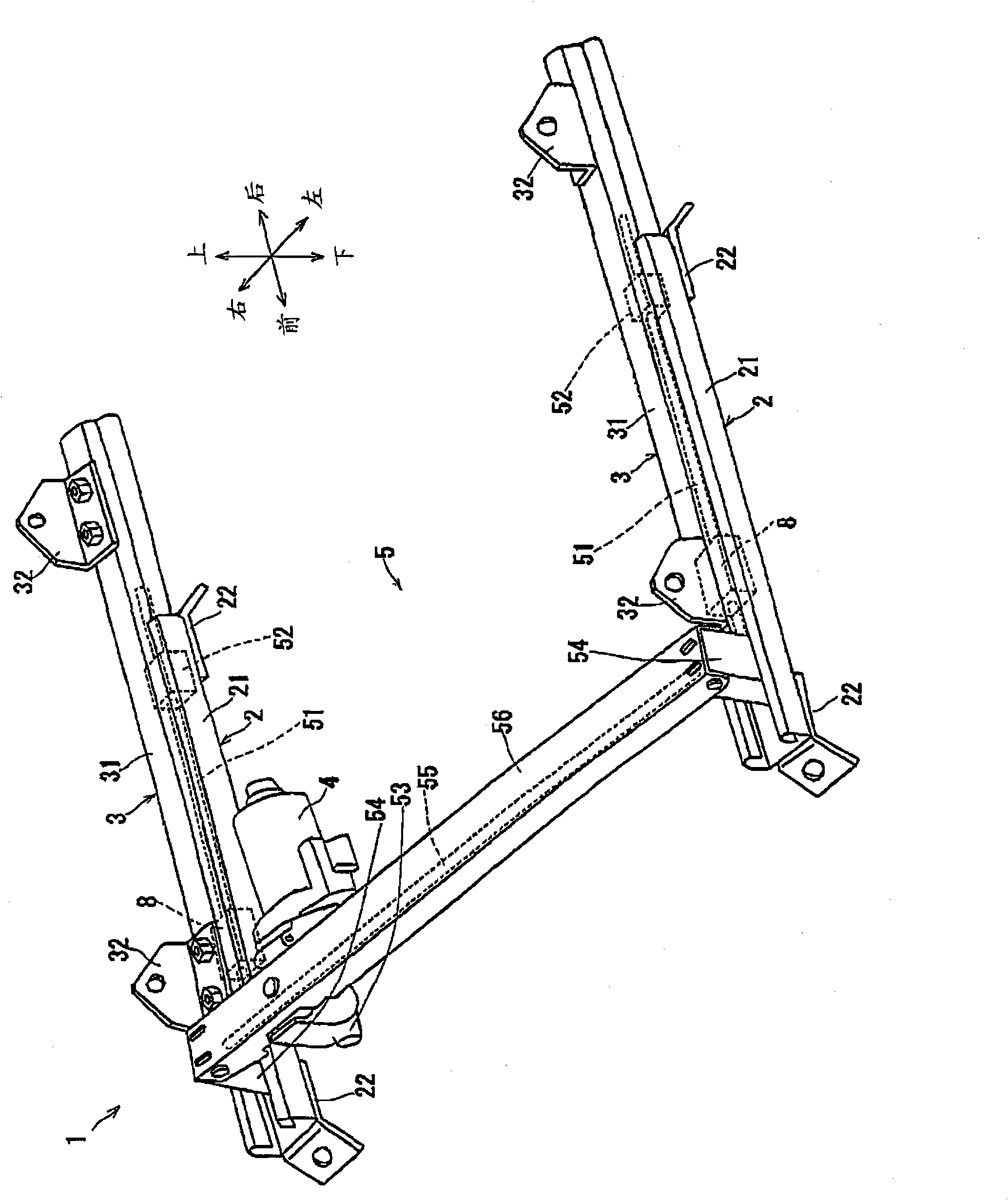
[0032] The following will refer to Figures 1 to 5 A first embodiment of the vehicle seat sliding apparatus 1 is described. According to the first embodiment, the vehicle seat sliding apparatus 1 is applied to a front seat of a vehicle. Directions such as "front", "rear", "left", "right" ("wide"), "upper" and "lower" used in the following description correspond to the front, rear, left and right ( width), top, bottom, etc.

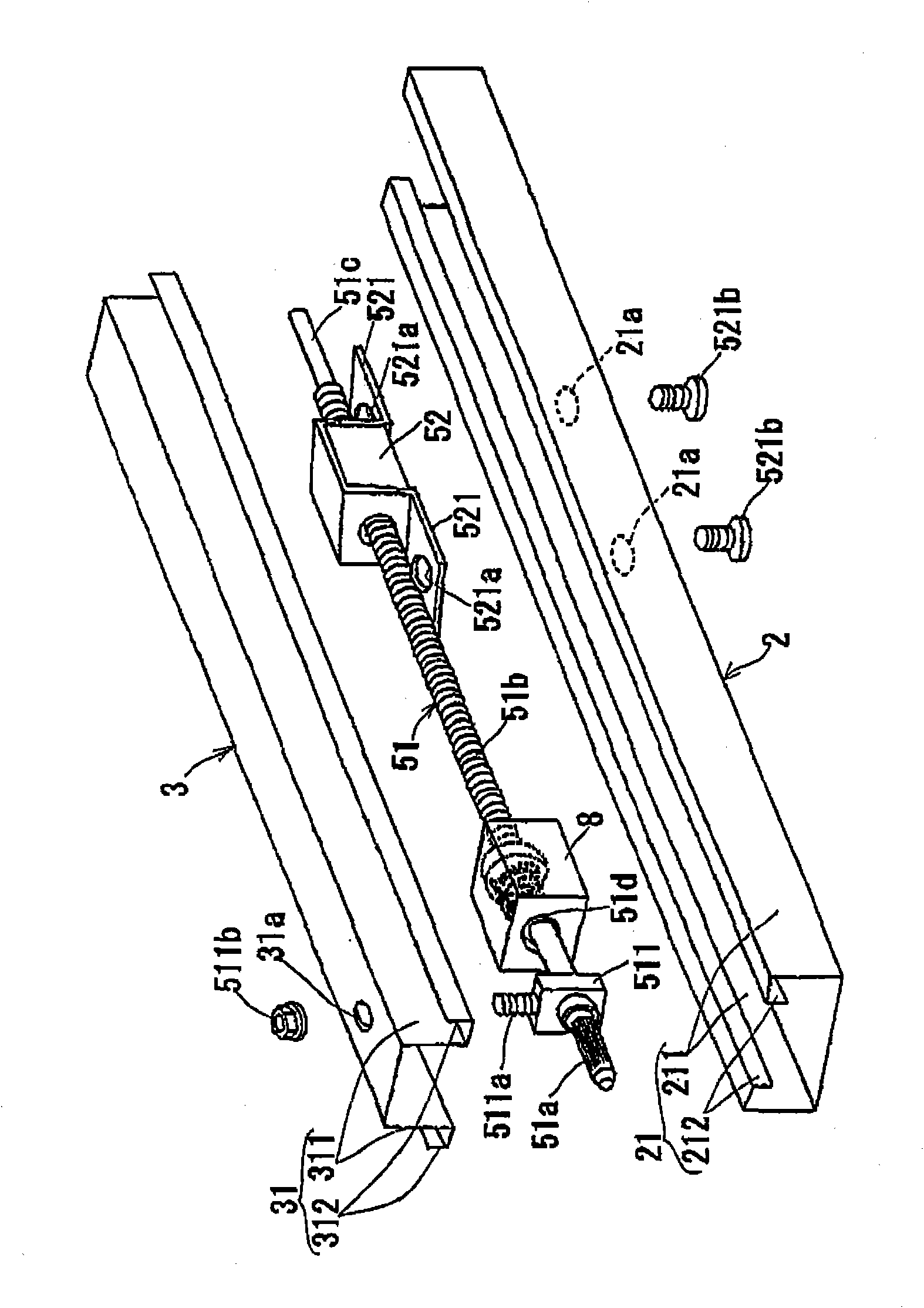
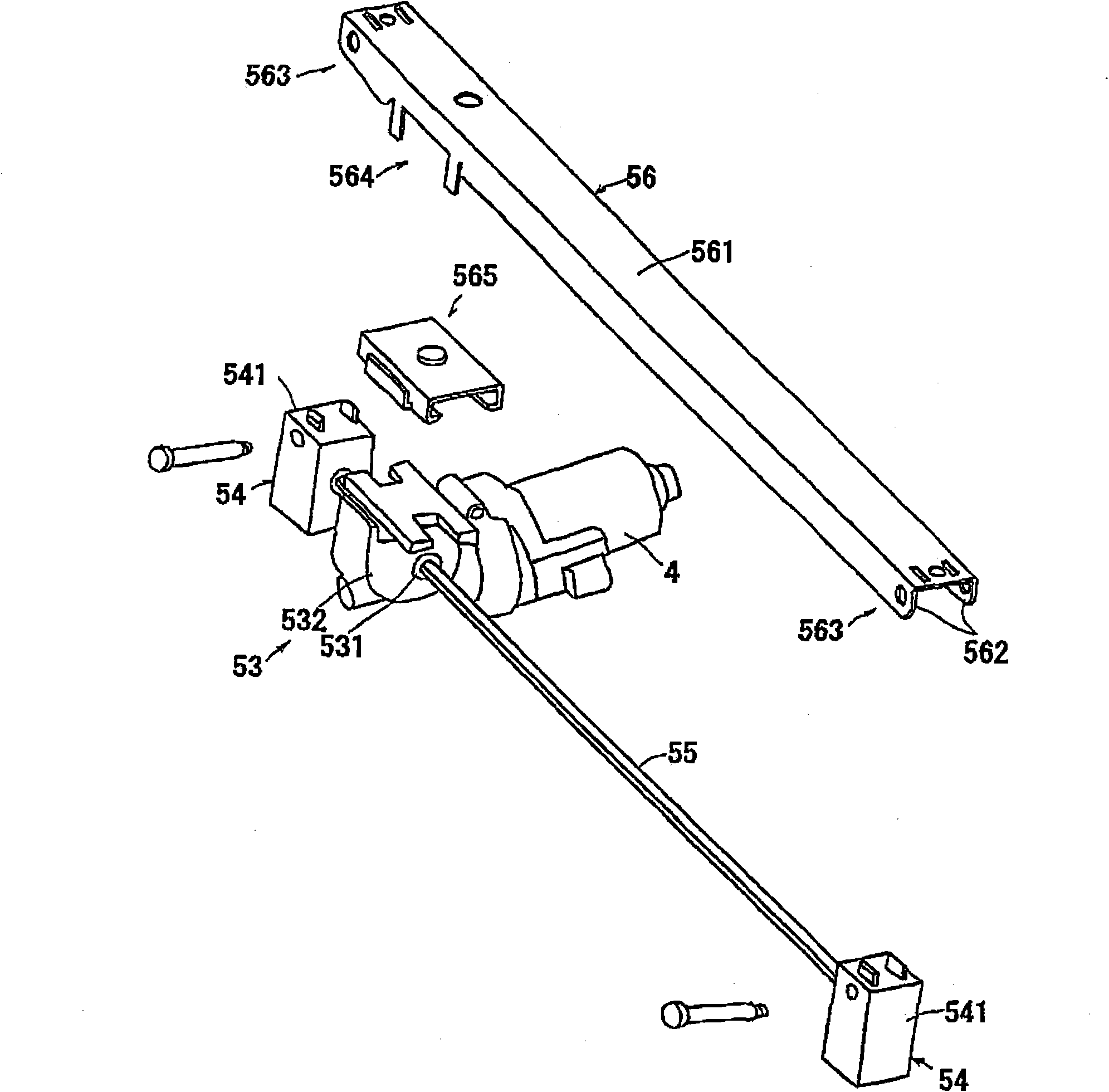
[0033] Such as figure 1 As shown in , the vehicle seat sliding device 1 includes a pair of lower rails 2 (right lower rail and left lower rail), a pair of upper rails 3 (right upper rail and left upper rail), a motor 4, a transmission mechanism 5 and a pair of sliding resistance applying devices 8 (right sliding resistance applying means and left sliding resistance applying means) (sliding resistance applying part). The lower left rail and the lower right rail 2 include substantially the same structure and function as each other. Therefore, the follow...

no. 2 approach

[0055] The following will refer to Figure 6-8 A vehicle seat sliding apparatus according to a second embodiment is described. In the following description, structures similar to those of the first embodiment are denoted by the same reference numerals. In addition, detailed descriptions of similar structures will be omitted and only different structures will be described in detail. In the first embodiment, the sliding resistance applying device 8 is provided on the screw shaft 51 . However, in the second embodiment, the sliding resistance applying device 9 is provided on the propeller shaft 55 . Therefore, the case body 81 and the coil spring 82 of the sliding resistance applying device 9 are configured similarly to those in the first embodiment, but the structure of the bush 93 is different from that in the first embodiment.

[0056] The bush 93 has a structure similar to that of the bush 83 of the first embodiment, of the large-diameter portion 831 , the small-diameter po...


PUM


Abstract

A seat slide apparatus (1) for a vehicle includes: a plurality of lower rails (2) adapted to be fixed at a floor of the vehicle in an inclining manner relative to the floor of the vehicle; a plurality of upper rails (3) adapted to be slidably supported by the lower rails (2), respectively, and to support a seat for the vehicle; a motor (4) generating a driving force for moving the upper rails (3) in a manner where the upper rails (3) slide relative to the corresponding lower rails (2); a transmitting mechanism (5) transmitting the driving force of the motor (4) to the upper rails (3); and at least one slide-resistance applying portion (8, 9) provided in the transmitting mechanism and applying an increased slide resistance to the transmitting mechanism when the upper rails move to slide downwardly on the inclination while applying a decreased slide resistance to the transmitting mechanism when the upper rails move to slide upwardly on the inclination.

Description

technical field [0001] The present invention relates to a seat slide apparatus for a vehicle, which moves a vehicle seat in a vehicle front-rear direction by a motor. Background technique [0002] Generally, a seat lifting apparatus for a vehicle moves a vehicle seat (a driven side member) in an up and down direction of a vehicle by rotating a motor (a driving side member), the seat raising apparatus includes a braking device, and when the vehicle seat When an excessive load is applied to the motor, the braking device limits the reverse rotation of the motor. For example, JPS59-117922A discloses a coupling device used as a brake device, which is characterized in that a coil spring is used. More specifically, the connecting device includes a driving part, a driven part, a small-diameter coil spring and a large-diameter coil spring, all of which are accommodated in the casing. When the driving part rotates, the diameter of the small-diameter coil spring expands and is spaced...

Claims


Application Information

Patent Timeline
Patent Type & Authority Applications(China)
IPC IPC(8): B60N2/07B60N2/90
CPCB60N2002/024B60N2/074B60N2/067B60N2/02258B60N2/02246
Inventor 古贺义孝
Owner AISIN SEIKI KK
Why Eureka
Try Eureka