
Reinforced concrete internal mold with multi-direction fixed supports

A technology of reinforced concrete and fixed supports, which is applied to formwork/formwork/work frame, on-site preparation of building components, building components, etc. Strong impact and anti-floating ability, high floor hollowness, good self-stability

Inactive Publication Date: 2011-03-23
林荣
View PDF0 Cites 2 Cited by
  • Summary
  • Abstract
  • Description
  • Claims
  • Application Information

AI Technical Summary

Problems solved by technology

[0003] (1) It is inconvenient to install, and it is necessary to add additional connectors to fix the inner mold, and the construction efficiency is low;
[0004] (2) The position of the inner mold is difficult to locate according to the design requirements, and the inner mold is easy to shift under the action of buoyancy and impact force during the construction process;
[0005] (3) Poor buoyancy resistance
[0006] (4) High installation cost
The cost of the project is increased due to the cumbersome construction procedures, low work efficiency, and the need to install additional connectors to fix the inner mold;
[0007] (5) At present, the inner molds used in engineering mostly use cement pipes, which are heavy, inconvenient for transportation, and easy to be damaged
However, the cost of the metal pipe is too high, the strength of the paper pipe is insufficient, and it is difficult to bear the construction load and the pressure of the concrete, which are not ideal.
[0008] (6) With one-way self-stabilizing type, because of its single fixing direction, it cannot meet the multi-directional fixing requirements

Method used


Image

  • Reinforced concrete internal mold with multi-direction fixed supports
  • Reinforced concrete internal mold with multi-direction fixed supports
  • Reinforced concrete internal mold with multi-direction fixed supports

Examples


Embodiment Construction

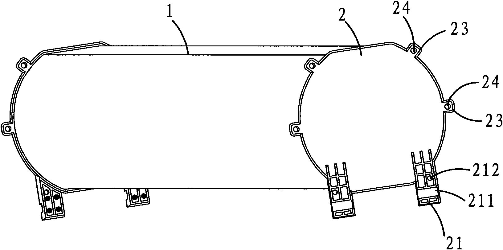
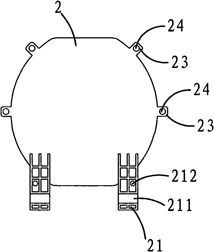
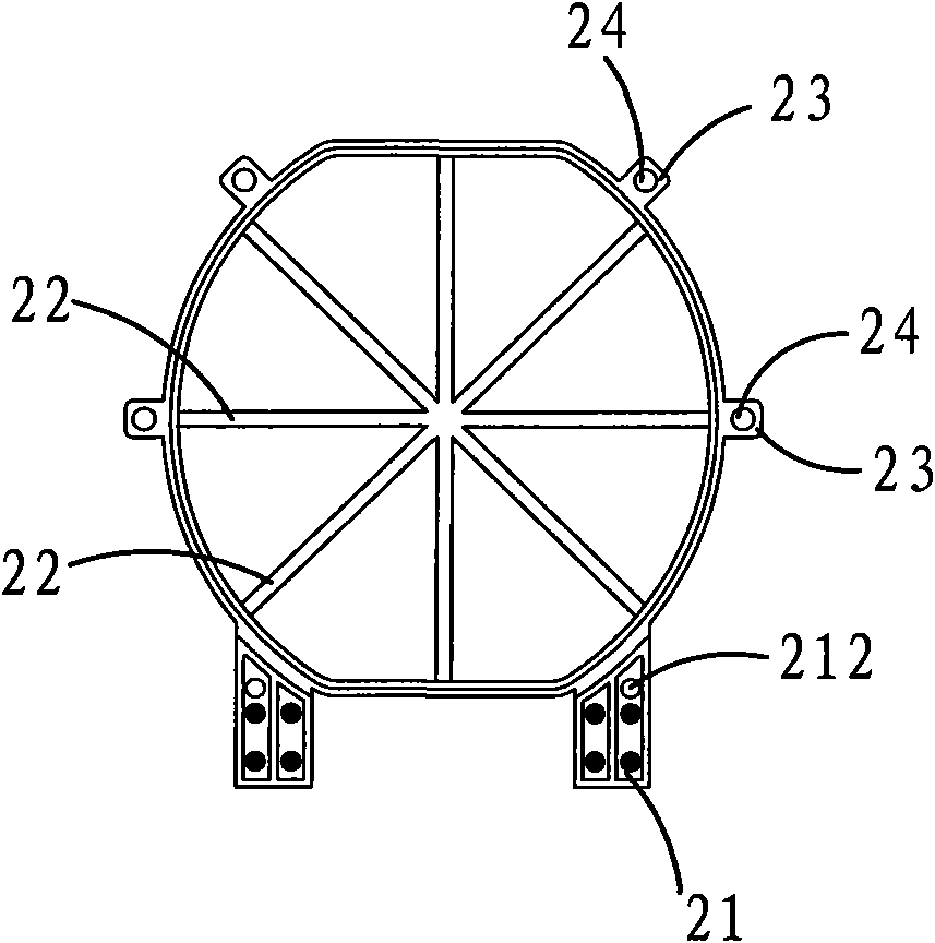
[0027] Please also see figure 1 , 2 , 3 and 4 are structural representations of the concrete inner mold with multi-directional fixed brackets of the present invention, a reinforced concrete inner mold with multi-directional fixed brackets, comprising a hollow cylinder 1 and end caps 2 at both ends, the hollow Cylinder 1 is a quasi-circular hollow cylinder, and its cross-sectional shape is a quasi-circular shape in which the upper and lower sides are straight and the left and right sides are arcs by cutting off the circular arcs at the top and bottom of the circle. The hollow cylinder is The PVC sheet is welded by ultrasonic waves. The section of the end cover 2 is corresponding to the hollow cylinder 1 to form a quasi-circular shape. The bottom of the end cover 2 is provided with two positioning pins 21, and the lower end of the positioning pins 21 is provided with a card slot 211 and a connection in a direction parallel to the end cover. In the hole 212 , two pairs of fixin...


PUM


Abstract

The invention relates to a reinforced concrete internal mold, in particular to a reinforced concrete internal mold with multi-direction fixed supports, which comprises a hollow cylinder and end covers at two ends, wherein positioning pins are arranged at the bottom of each of the end covers; clamping grooves and connecting holes are arranged on the positioning pins; the hollow cylinder is a quasi-circular cylinder; the cross section of the hollow cylinder is in the shape of a quasi-circle formed by cutting part of circular arcs at the top and the bottom of a circle, wherein the upper side and the lower side of the quasi-circle are straight, and the left side and the right side of the quasi-circle are circular arcs; each end cover is in the shape of a quasi-circle corresponding to the cross section of the hollow cylinder; at least a pair of fixed supports are arranged in the positions of circular arc sections at the left side and the right side of each end cover; positioning holes are arranged on the fixed supports; a plurality of fixed supports are uniformly arranged on the inner wall of each end cover along the radial direction; and the hollow cylinder is formed by ultrasonic welding of PVC sheets. The invention has the advantages of convenient positioning and easy construction, can not generate displacement easily, and can obtain higher hollow ratio of floor slabs.

Description

【Technical field】 [0001] The invention relates to an inner form for a building floor, in particular to a reinforced concrete inner form used in the technology of cast-in-place hollow floor slabs. 【Background technique】 [0002] Reinforced concrete inner formwork is an important component used to manufacture concrete slab structures. Its main function is to hollow out the concrete, reduce the structural weight of the slab, and improve the mechanical performance of the slab structure at the same time. The cast-in-place hollow slab generally includes reinforced concrete, a hollow inner mold, and the two ends of the hollow inner mold are sealed by plugs. The hollow inner mold is wrapped in the cast-in-place reinforced concrete, and ribs are formed between the thin-walled tubes. There are steel bars connecting between them, so the cast-in-place reinforced concrete hollow floor slab composed of hollow membrane, steel bar and concrete has good force bearing and force transmission p...

Claims


Application Information

Patent Timeline
IPC IPC(8): E04C1/00E04B5/36E04G15/06
Inventor 林荣
Owner 林荣
Learn More