Vertical shaft tidal current generating set

A tidal power generation, vertical axis technology, applied in the direction of tidal flow/damless hydropower, hydropower, ocean energy power generation, etc. The vertical self-weight load and horizontal impact load of the main shaft are large, so as to improve the starting performance and power generation efficiency, reduce the bending moment load and friction resistance of the main shaft, and increase the maximum horizontal load capacity.

Inactive Publication Date: 2011-03-23
HARBIN ENG UNIV
View PDF9 Cites 30 Cited by
  • Summary
  • Abstract
  • Description
  • Claims
  • Application Information

AI Technical Summary

Problems solved by technology

Harbin Engineering University has carried out tidal current power generation research for many years, and concluded that the traditional vertical axis tidal current power generation device has the following problems in power generation: (1) When the main shaft of the impeller rotates with a single support, the main shaft has a large bending moment load, and the structural strength of the main shaft is relatively high. high
When the main shaft of the impeller rotates with double supports, due to the deformation of the device, the friction of the main shaft increases, which affects the start-up and power generation performance of the tidal current power generation device; (2) the self-starting performance and power generation performance of the impeller of the fixed-blade vertical-axis tidal current power generation device are relatively poor; (3 ) The vertical self-weight load and horizontal impact load of the impeller and main shaft of the large-scale vertical axis tidal current power generation device are relatively large, and the structural strength requirements of the impeller and main shaft are relatively high, and the device is not suitable for large-scale development; (4) The application platform and use environment are single , not conducive to large-scale production and application

Method used


Image

  • Vertical shaft tidal current generating set
  • Vertical shaft tidal current generating set
  • Vertical shaft tidal current generating set

Examples


Embodiment Construction

[0023] The present invention is described in detail below in conjunction with accompanying drawing example:

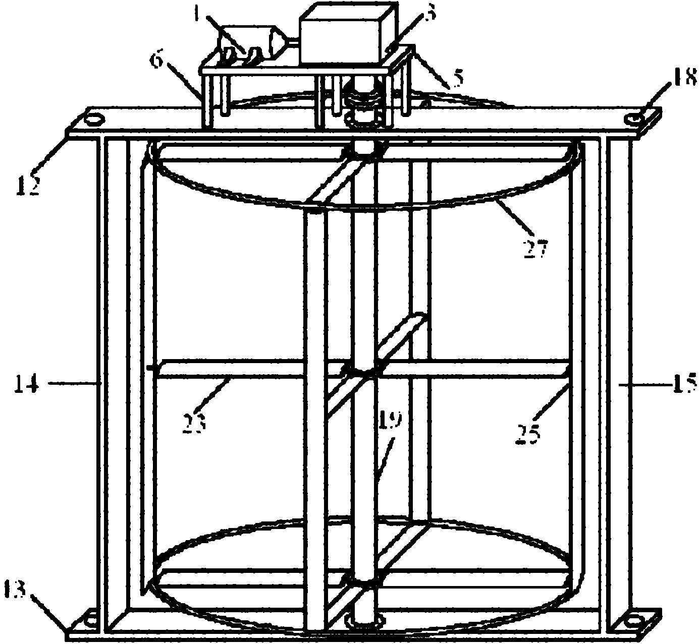
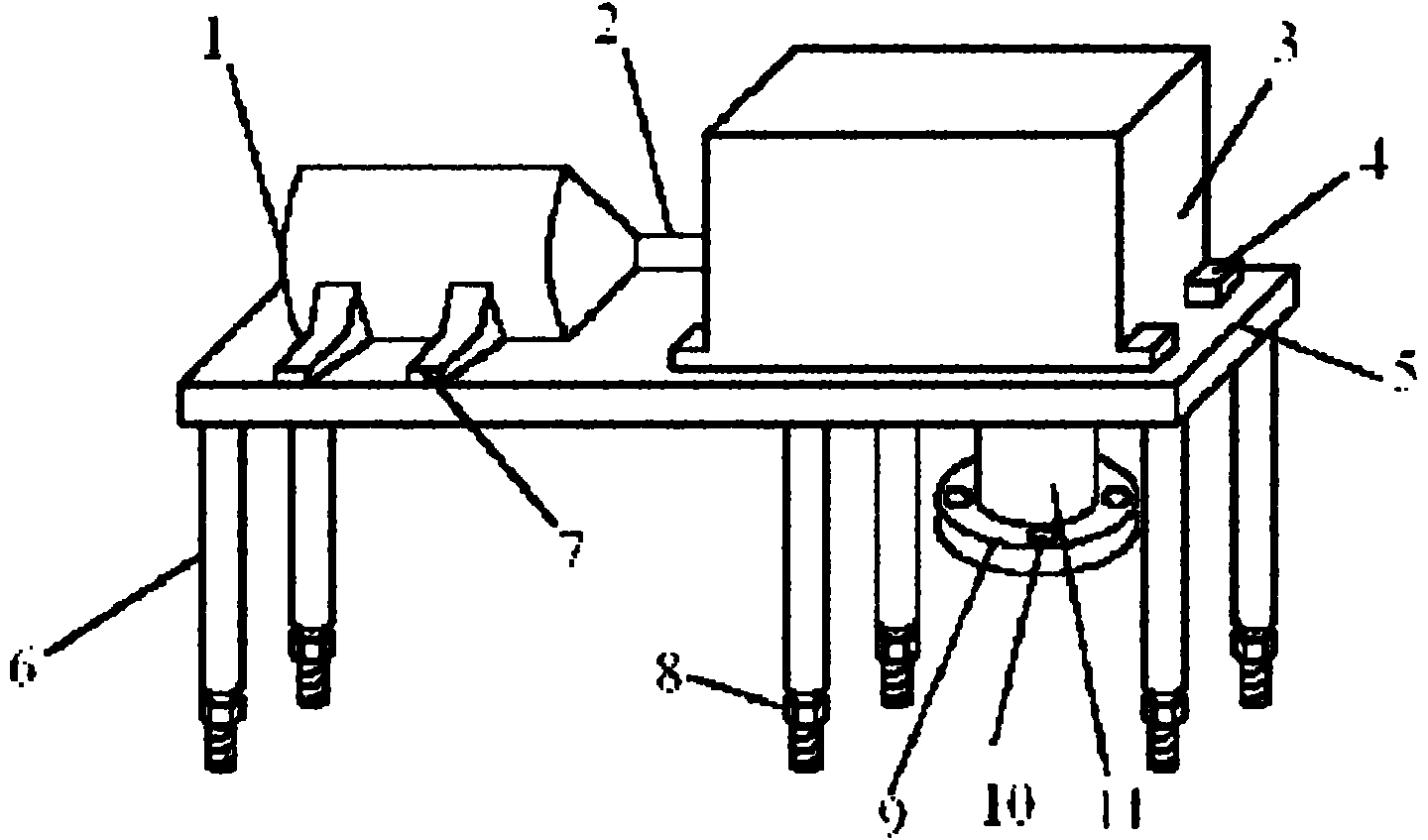
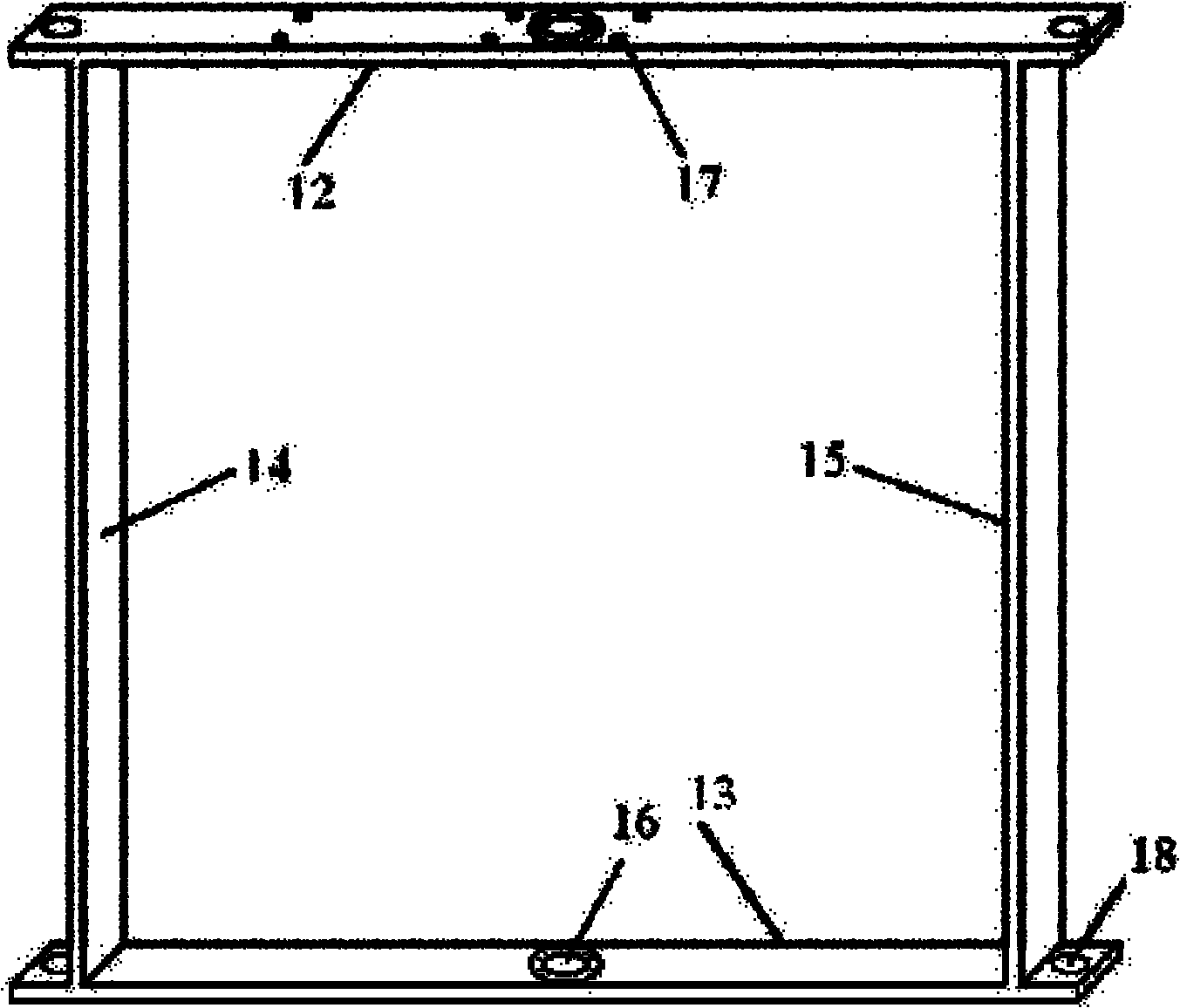
[0024] Such as figure 1 , figure 2 , image 3 and Figure 4 As shown, the patent of the present invention includes three modules of the upper platform part, the support frame part and the impeller part.

[0025] The upper platform part includes a generator 1, a horizontal connecting shaft 2, a gearbox 3, a gearbox seat 4, a supporting platform 5, six pillars 6, a generator seat 7, six rotating bolts 8, a vertical Connecting shaft flange 9, and a vertical connecting shaft 11. The support platform 5 is supported by six pillars 6 and fixed on the upper frame plate 12 by six rotating bolts 8 . The left end of the support platform 5 is provided with a generator 1 and the right end is provided with a gear box 3 . The gearbox 3 and the generator 1 are connected through a horizontal connection shaft 2 . The generator 1 is provided with a generator base 7, the gear box ...


PUM


Abstract

The invention provides a vertical shaft tidal current generating set. The vertical shaft tidal current generating set comprises three modules, namely an upper layer platform part, a supporting frame part and an impeller part, wherein the upper layer platform part mainly comprises a generator, a gear box, a horizontal connecting shaft, a supporting platform, a supporting column and a vertical connecting shaft; the supporting frame part is formed by connecting an upper frame plate, a lower frame plate, a left frame plate and a right frame plate; and the impeller part comprises a main shaft, a spoke sleeve, a spoke, a spoke shaft, a blade, a blade shaft, a wheel disk and an adaptive attack angle control device. The invention provides the high-performance vertical shaft tidal current generating set, which has high starting and generating performances and high structural strength, can be developed towards large-scale direction, can be used below a floating platform and above a pile base and a tension leg, is convenient to produce, manufacture, install and debug, and is suitable for engineering application.

Description

technical field [0001] The invention relates to a vertical axis tidal current power generation device, which belongs to the field of hydraulic machinery and hydraulic generators. Background technique [0002] Tidal energy refers to the kinetic energy of seawater flow, mainly the relatively stable flow in submarine channels and straits and the regular seawater flow caused by tides. As a renewable energy source, tidal current energy is rich in reserves and widely distributed, and has excellent development prospects and value. my country's exploitable tidal current energy resources rank first in the world, and how to utilize tidal current energy resources has important practical significance. [0003] The main way to utilize tidal current energy is to generate electricity. Its working principle is similar to that of wind power generation and conventional hydropower generation, that is, the kinetic energy of seawater is converted into electrical energy through an energy convers...

Claims


Application Information

Patent Timeline
Patent Type & Authority Applications(China)
IPC IPC(8): F03B13/26F03B11/06F03B11/00
CPCY02E10/226Y02E10/28Y02E10/20Y02E10/30Y02P70/50
Inventor 张亮马勇张楠张学伟盛其虎
Owner HARBIN ENG UNIV
Why Eureka
Try Eureka