

Battery system and electric vehicle including the same
A battery system and electric vehicle technology, applied in electric vehicles, batteries, secondary batteries, etc., can solve problems such as rising costs and complicated battery system structure, and achieve the effect of increasing driving time and low cost
- Summary
- Abstract
- Description
- Claims
- Application Information
AI Technical Summary
Problems solved by technology
Method used
Image

Examples
Embodiment approach
[0064] Hereinafter, the battery system according to the first embodiment will be described with reference to the drawings. In addition, the battery system according to the present embodiment is mounted on an electric vehicle (for example, an electric vehicle) that uses electric power as a driving source.
[0065] (1) Structure of the battery system
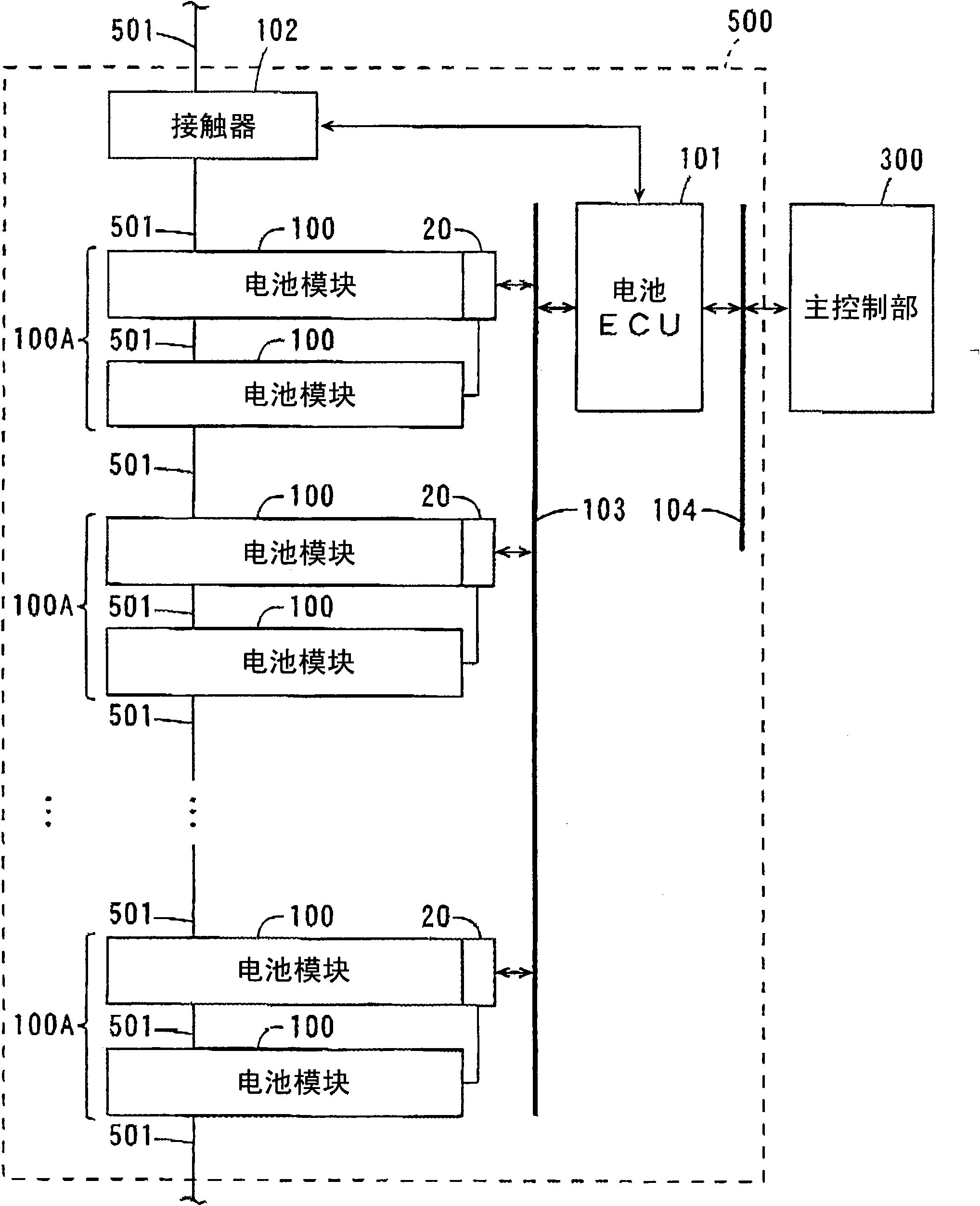
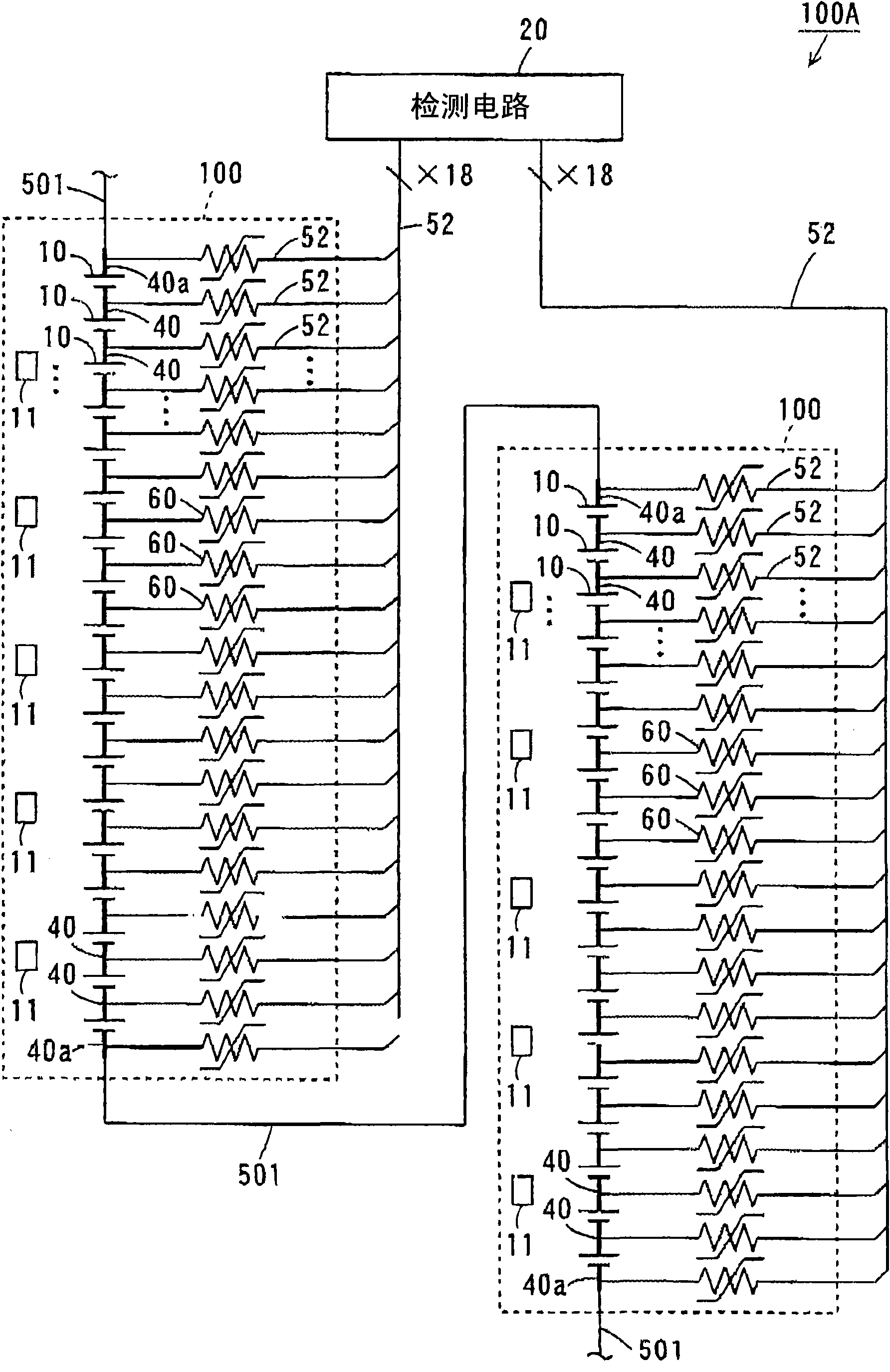
[0066] figure 1 A block diagram showing a schematic configuration of the battery system according to the first embodiment. Such as figure 1 As shown, the battery system 500 mainly includes: a plurality of battery modules 100, a plurality of detection circuits 20, a battery ECU (Electronic Control Unit: electronic control unit) 101 and a contactor (contactor) 102, the battery system 500 is connected via a bus (bus) 104 It is connected to the main control unit 300 of the electric vehicle. In addition, this battery system 500 has a casing (casing) which is not shown. Each component of the battery system 500 is housed in the case...
no. 2 Embodiment approach
[0145] Differences between the battery system according to the second embodiment and the battery system 500 according to the first embodiment will be described.
[0146] Figure 11 It is a plan view showing the arrangement of module groups included in the battery system according to the second embodiment.
[0147] In the battery system according to this embodiment, if Figure 11 As shown, the module group 100B includes three sets of battery modules 100a, 100b, and 100c. One detection circuit 20 is commonly provided in the three battery modules 100a, 100b, and 100c.
[0148] In the present embodiment, three sets of battery modules 100c, 100b, and 100a are arranged in a row along the X direction (direction in which a plurality of battery cells 10 are arranged) in this order.
[0149] The printed circuit board 21 including the detection circuit 20 is mounted on the end surface of one battery module 100a between the end surfaces of the battery modules 100a and 100b that are clo...
no. 5 Embodiment approach
[0174] Differences between the battery system according to the fifth embodiment and the battery system 500 according to the first embodiment will be described.
[0175] Figure 14 (a) is a plan view showing the arrangement of module groups in the battery system according to the fifth embodiment, Figure 14 (b) is viewed from one end face side Figure 14 (a) End view of the module cluster.
[0176] In the battery system according to this embodiment, if Figure 14 As shown in (a), the module group 100E includes three sets of battery modules 100a, 100b, and 100c. One detection circuit 20 is commonly provided in the three battery pack modules 100a, 100b, and 100c.
[0177] In the present embodiment, three sets of battery modules 100c, 100b, and 100a are arranged in a row along the X direction (direction in which a plurality of battery cells 10 are arranged side by side). The three sets of battery modules 100a, 100b, and 100c are arranged in this order in the Y direction (dire...
PUM
 Abstract
Description
Claims
Application Information