Cutter clamping device

A technology of tool clamping and clamping jaws, which is applied in the direction of the chuck, etc., can solve the problems of long tool change time, wear and deformation of the spindle, increased time for advancing, withdrawing and changing tools, etc., so as to simplify the action of tool changing and shorten the Tool change time and power energy saving effect

Inactive Publication Date: 2012-03-21
FACTORY AUTOMATION TECH CO LTD
View PDF1 Cites 4 Cited by
  • Summary
  • Abstract
  • Description
  • Claims
  • Application Information

AI Technical Summary

Problems solved by technology

[0004] Please refer to U.S. Bulletin No. 6238152, which is an existing tool clamping device. It can be clearly seen from the diagram that its spring group is directly seated in the shaft hole of the main shaft, and is supported by the shaft of the main shaft. The inner wall of the shaft hole, according to this, when the tool is retracted, the compressed spring group supports the main shaft, causing the main shaft to wear and deform, and then the bearing covering the main shaft is compressed and damaged. This is its defect one;
[0005] Furthermore, in the tool clamping device of the U.S. announcement No. 6238152, when retracting the tool, the tool retracting device must apply a force greater than that produced by its spring group to the force bar, and continue to apply force until the tool withdraws ( like Figure 10 As shown), in addition, its advance and retreat strokes are extremely long, resulting in a relatively increased time for advance, retreat and tool replacement, and the situation of improper loss of manufacturing process time is its defect two.
[0006] Please also refer to the tool clamping device shown in US Bulletin No. 5662442. There is also a spring set directly seated in the shaft hole of the spindle. The lack of damage to the bearing outside the main shaft due to compression;
[0007] In addition, the tool clamping device of the U.S. announcement No. 5662442 adopts a large-diameter spring group in order to increase the clamping force on the tool. In this way, the diameter of the main shaft must be increased relatively. After that, the centrifugal force increases when the spindle rotates, and the phenomenon of vibration occurs when the spindle operates, which in turn leads to the reduction of the precision of the tool held by the spindle during processing, and in the case of large centrifugal force and high vibration of the spindle. There are disadvantages of unfavorable spindle high-speed operation
[0008] Therefore, in view of the above-mentioned tool clamping device, the main shaft and bearing are prone to damage, inaccurate processing, and long tool change time, etc., the inventors developed and improved the tool clamping device in order to exert its higher practicality. benefit

Method used


Image

  • Cutter clamping device
  • Cutter clamping device
  • Cutter clamping device

Examples


Embodiment Construction

[0064] In order to have a clearer understanding of the technical features, purposes and effects of the present invention, the specific implementation manners of the present invention will now be described with reference to the accompanying drawings.

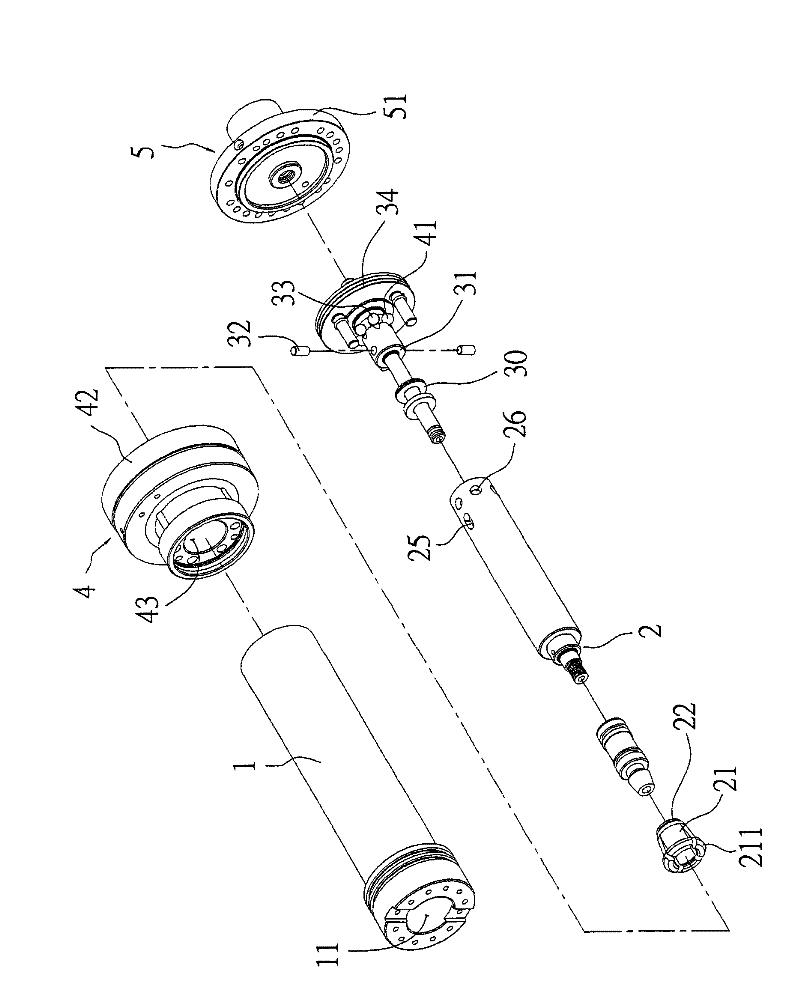
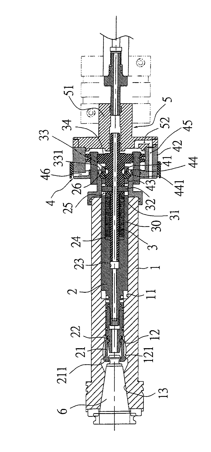
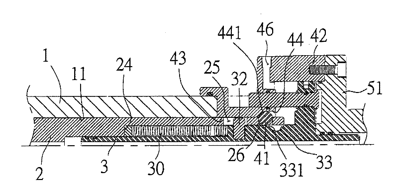
[0065] First, see figure 1 , figure 2 As shown, the tool clamping device of the present invention mainly includes a main shaft [spindle] 1, a pull bar [drawbar] 2, a force bar [push bar] 3, a double force mechanism [power intensifier] 4 and a power source 5; wherein:

[0066] The main shaft (spindle) 1 is provided with a shaft hole 11, and a jaw action section 12 is formed at one end of the shaft hole 11, and the jaw action section 12 is protruded with a contact portion 121, and then the jaw action section 12 extends A tapered cutter cylinder clamping section 13 is formed.

[0067] The drawbar [drawbar] 2 is set in the shaft hole 11 of the main shaft 1, and a clamping jaw 21 is set at one end, and an elastic member 22 is set ...


PUM


Abstract

The invention relates to a cutter clamping device. The device is mainly characterized in that a drawbar is arranged in a spindle hole, and a spring set and a push bar are arranged in the draw bar to ensure that the spring set is arranged between the drawbar and the push bar. By using the cutter clamping device of the invention, when the cutter is retracted, the compressed spring set can not directly support and press the spindle hole and damage the bearing covered outside the spindle; and the design of the power intensifier with high amplification factor is utilized to clamp the cutter with the spring set with the least springs and the minimum diameter and the diameter of the spindle is reduced, thus the centrifugal force generated by the rotation of the spindle can be reduced and vibrations can be avoided when the spindle runs so that the condition of inaccurate finished surface can be prevented; and the high-speed actuation of the spindle can be facilitated while the diameter and length of the spindle are reduced.

Description

technical field [0001] The invention relates to a clamping device, especially a clamping device that can prevent the outer bearing of the covered spindle from being pressed by the spring set against the shaft hole of the spindle, and can avoid the inaccurate processing surface caused by the shaking of the spindle when the spindle is in motion. Tool clamping device. Background technique [0002] The main shaft of a general processing machine (such as: a milling machine) is connected to a gripper by a pull rod that goes through the main shaft, and then the gripper clamps the cutter barrel to drive the tool assembled by the cutter barrel to rotate at high speed to perform cutting operations on the workpiece. . [0003] When the tool cuts the workpiece, in order to prevent the tool cylinder from detaching from the jaws, a spring set (compression spring or disc spring) is usually set on the spindle, so that the elastic force of the spring set can be used to support and tighten t...

Claims


Application Information

Patent Timeline
Patent Type & Authority Patents(China)
IPC IPC(8): B23B31/24B23B31/26B23B31/30
Inventor 卢永祥林炳铄
Owner FACTORY AUTOMATION TECH CO LTD
Why Eureka
Try Eureka