Structure and method of assembling and disassembling a rear wheel of a motor bicycle

A motor two-wheeled vehicle and rear wheel technology, which is applied to bicycle accessories, bicycle brakes and other directions, can solve the problems of time-consuming rear wheel loading and unloading operations, complicated and other problems, and achieve the effect of easy loading and unloading operations and easy loading and unloading operations.

Inactive Publication Date: 2011-03-30
HONDA MOTOR CO LTD
View PDF10 Cites 2 Cited by
  • Summary
  • Abstract
  • Description
  • Claims
  • Application Information

AI Technical Summary

Problems solved by technology

[0005] However, the torsion bar usually intersects with the rear shock absorber disposed on the outer side thereof in a side view, and the rear shock absorber becomes an obstacle when the torsion bar rotates outward, so it takes time to remove the rear shock absorber. Problems complicating loading and unloading of rear wheels

Method used


Image

  • Structure and method of assembling and disassembling a rear wheel of a motor bicycle
  • Structure and method of assembling and disassembling a rear wheel of a motor bicycle
  • Structure and method of assembling and disassembling a rear wheel of a motor bicycle

Examples


Embodiment 1

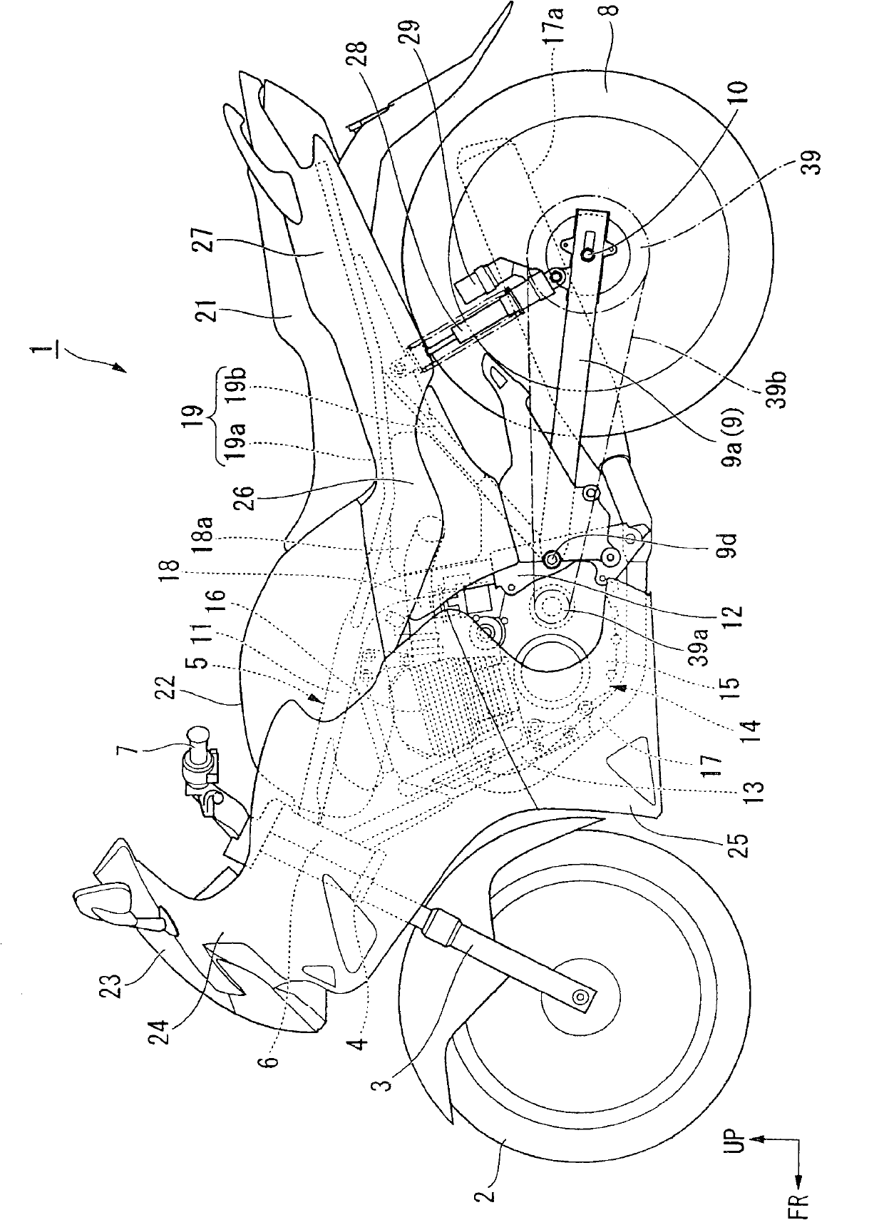
[0067] exist figure 1 In the shown motorcycle (saddle type vehicle) 1 , the front wheels 2 are pivotally supported by the lower ends of a pair of front forks 3 . The upper portion of each front fork 3 is pivotally supported on a head pipe 6 at the front end of a vehicle frame 5 via a steering rod 4 so as to be steerable. A handle 7 for steering the front wheels is attached to the upper portion of the steering rod 4 . A rear wheel (drive wheel) 8 of the motorcycle 1 is pivotally supported by a rear end portion of a swing arm 9 .

[0068] The frame 5 is mainly composed of a main frame 11 that extends rearward from an upper portion of the head pipe 6 and then bends downward. A pivot bracket 12 that supports the front end of the swing arm 9 is integrally provided on the rear lower side of the main frame 11 . The down frame 13 extends obliquely downward from the lower portion of the head pipe 6 . A front end portion of a crankcase 15 of an engine 14 mounted inside the frame 5 i...

Embodiment 2

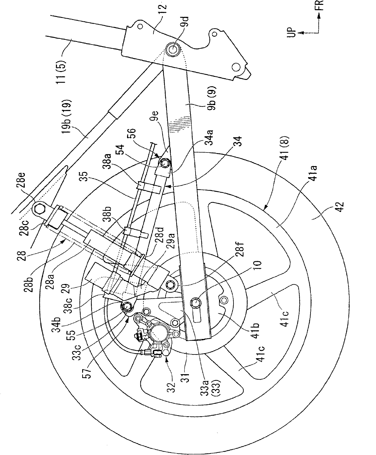
[0140] refer to Figure 12 , 13 A second embodiment of the present invention will be described.

[0141] Compared with the above-mentioned first embodiment, the main difference of this embodiment is that the rear wheel 8 side including the brake disc 31 has an opening 61 for the brake caliper 32 detached from the brake disc 31 to enter. The parts that are the same as those in the above-mentioned embodiments are denoted by the same symbols, and description thereof will be omitted.

[0142] refer to Figure 12 The opening 61 is surrounded by the inner peripheral edge of the rim portion 41 a , the side edge of the adjacent spoke portion 41 c and the outer peripheral edge of the brake disc 31 in side view. The opening 61 is set to a size allowing at least the inner portion 32b of the brake rotor 32 to enter (preferably a size allowing only the caliper 32 and the caliper bracket 33 to enter).

[0143] Thus, even if the brake caliper 32 and the caliper bracket 33 are not complet...


PUM


Abstract

The present invention provides a structure and method of assembling and disassembling a rear wheel of a motor bicycle, in which the rear wheel can be transversally puller out and inserted into a drive member which rotates along an engine to embed, such that an operation of assembling and disassembling the rear wheel is easy without assemble and disassemble of a rear buffer or a disk brake. In the structure, a front end part (34a) of a torsion bar (34) is connected to an arm swing (9) in a manner of swinging up and down through a front connection shaft (54) in a left-right direction, a front connection part (56) of connecting the front end part (34a) of the torsion bar (34) and the arm swing (9) allows the torsion bar (34) to swing outwards, thereby, the torsion bar (34), a tongs bracket (33) and a brake tongs (32) can swing up and down to a position where the rear wheel (8) can move to one side of a right arm member (9b).

Description

technical field [0001] The invention relates to a rear wheel loading and unloading structure and method of a two-wheeled motor vehicle. Background technique [0002] Conventionally, in the rear wheel portion of a motorcycle, a drive member that rotates with the engine, a rear wheel that can be pulled out and inserted from the lateral direction and fitted with the drive member on an axle provided at the rear portion of the swing arm, A brake disc fixed to the side of the rear wheel opposite to the drive member, and a caliper bracket supporting a caliper that clamps the brake disc, and the brake caliper and caliper bracket are connected to each other via a torsion bar. arm swing. The front end portion of the torsion bar is rotatably coupled to the swing arm via a longitudinal axis perpendicular to the left-right direction (for example, refer to Patent Document 1). [0003] In this structure, when attaching and detaching the rear wheel, after the brake caliper is moved upward...

Claims


Application Information

Patent Timeline
Patent Type & Authority Applications(China)
IPC IPC(8): B62L1/02
Inventor 三星满津子足海孝
Owner HONDA MOTOR CO LTD
Why Eureka
Try Eureka