Common mode filter

A common-mode filter and conductor technology, applied in transformers, inductors, fixed transformers, etc., can solve the problems of small electrode coupling coefficient and low self-resonance frequency, achieve small parasitic capacitance, increase coupling coefficient, and improve self-resonance The effect of frequency

Inactive Publication Date: 2011-03-30
SHENZHEN ZHENHUA FU ELECTRONICS +1
View PDF0 Cites 8 Cited by
  • Summary
  • Abstract
  • Description
  • Claims
  • Application Information

AI Technical Summary

Problems solved by technology

[0003] The purpose of the embodiments of the present invention is to provide a common-mode filter, aiming to solve the problem that the existing common-mode filter is made in a planar manner, resulting in a small coupling coefficient between electrodes and the self-resonant frequency is low due to the up-and-down stacking method. question

Method used


Image

  • Common mode filter
  • Common mode filter
  • Common mode filter

Examples


Embodiment Construction

[0037] In order to make the object, technical solution and advantages of the present invention clearer, the present invention will be further described in detail below in conjunction with the accompanying drawings and embodiments. It should be understood that the specific embodiments described here are only used to explain the present invention, not to limit the present invention.

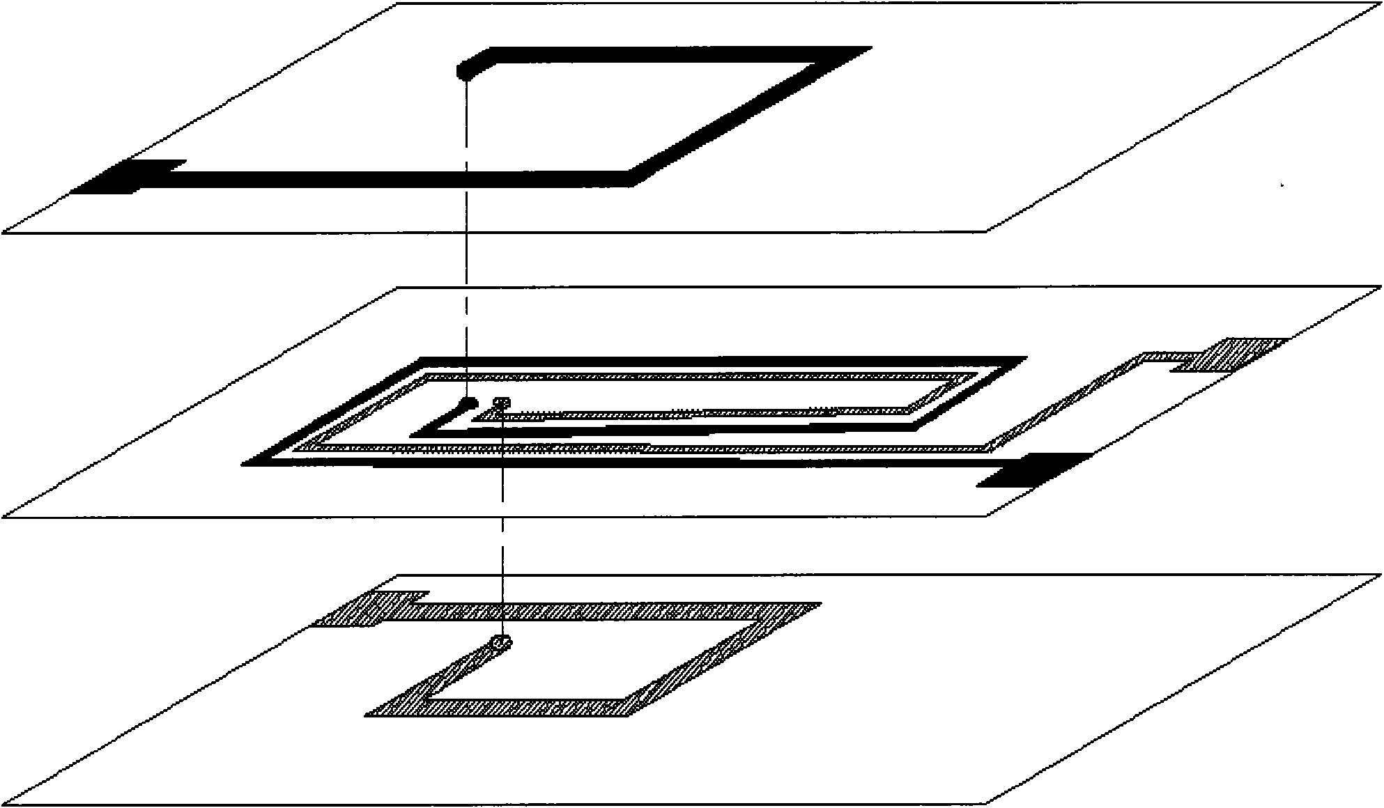
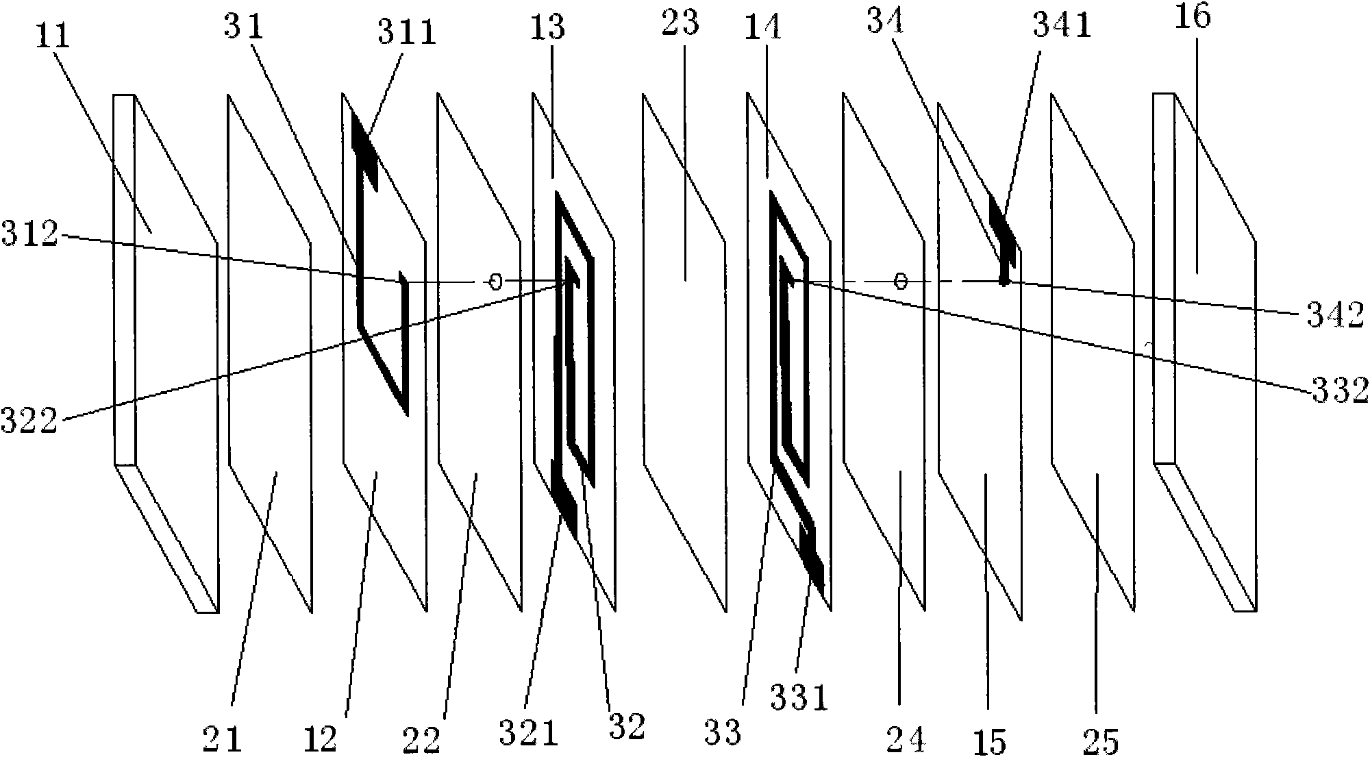
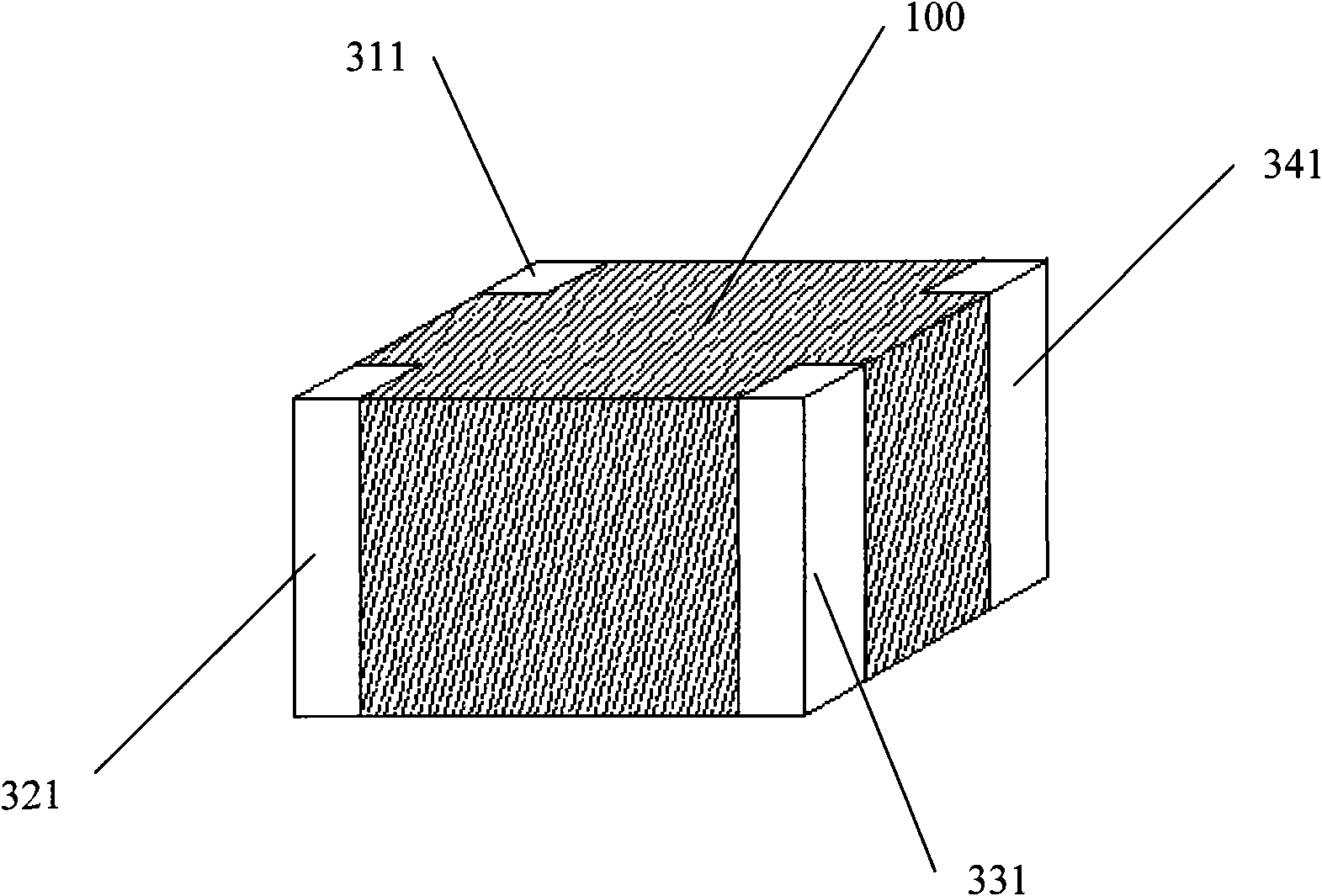
[0038] In the common mode filter provided by the embodiment of the present invention, a layer of dielectric layer made of composite material is printed between the first coil and the second coil, so that the coupling coefficient between the electrodes increases; at the same time, because its magnetic field lines are parallel to the ground , The parasitic capacitance is small, the self-resonant frequency is improved, and the suppression effect on common-mode interference is good.

[0039] The common mode filter decomposition structure provided by the embodiment of the present invention is as follows...


PUM


Abstract

The invention is applicable to the field of electronic elements and provides a common mode filter, which comprises a first insulation layer, a second insulation layer, a third insulation layer, a fourth insulation layer, a fifth insulation layer, a sixth insulation layer, a first medium layer, a second medium layer, a third medium layer, a fourth medium layer, a first conductor, a spiral second conductor, a spiral third conductor, a fourth conductor, a first lead-out electrode, a second lead-out electrode, a third lead-out electrode and a fourth lead-out electrode, wherein the first conductor and the second conductor form a first coil; the fourth conductor and the third conductor form a third coil; and the magnetic lines of force passing through the first and second coils are parallel to the ground. In the common mode filter of the invention, a medium layer made of a composite material is printed or cast between the first and second coils, so the coefficient of coupling between the electrodes increases; meanwhile, the magnetic lines of force are parallel to the ground, the parasitic capacitance is small, the resonant frequency is improves and the inhibition effect on common mode interference is desirable.

Description

technical field [0001] The invention belongs to the field of electronic components, in particular to a common mode filter. Background technique [0002] figure 1 The structure of the common-mode filter provided by the prior art is shown, which is made in a coplanar manner. The coupling coefficient between electrodes in this common-mode filter is small; in order to solve the problem of small coupling coefficient between electrodes, The existing technology proposes a common-mode filter made by stacking up and down. Although the coupling coefficient between the electrodes in this common-mode filter is large, the parasitic capacitance is relatively large because the magnetic field lines are perpendicular to the ground, so resulting in a relatively low self-resonant frequency. Contents of the invention [0003] The purpose of the embodiments of the present invention is to provide a common-mode filter, aiming to solve the problem that the existing common-mode filter is made in...

Claims


Application Information

Patent Timeline
Patent Type & Authority Applications(China)
IPC IPC(8): H01F17/00H01F37/00H01F27/28H01F30/06
Inventor 滕林丁晓鸿付贤民马建华黄寒寒於斌
Owner SHENZHEN ZHENHUA FU ELECTRONICS
Why Eureka
Try Eureka