Transmission system and method applied to wireless relay

A technology of wireless relay and transmission system, applied in the field of transmission system, can solve the problems of complicated switching process and unfavorable relay data transmission, etc.

Inactive Publication Date: 2011-03-30
深圳市恒程汇文化科技有限公司
View PDF2 Cites 14 Cited by
  • Summary
  • Abstract
  • Description
  • Claims
  • Application Information

AI Technical Summary

Problems solved by technology

The data reverse transmission path during handover will go from the core network element to the relay, and then return to the core network element through the same path, and then be routed to the access network element; on the other hand, for the LBO transmission channel where the access node is located in the DeNB architecture, since this transmission channel is established on the host base station that provides wireless access for it, so when the Relay itself is handed over, a new transmission channel needs to be established in the target DeNB, and multiple UEs embedded in this channel transmission channels need to be switched to new transmission channels respectively, and the switching process is complicated
It can be seen that Relay can only access a single transmission channel. Since each of the above two transmission channels has its own limitations, it is not conducive to the transmission of Relay data in scenarios such as switching.

Method used


Image

  • Transmission system and method applied to wireless relay
  • Transmission system and method applied to wireless relay
  • Transmission system and method applied to wireless relay

Examples


example 1

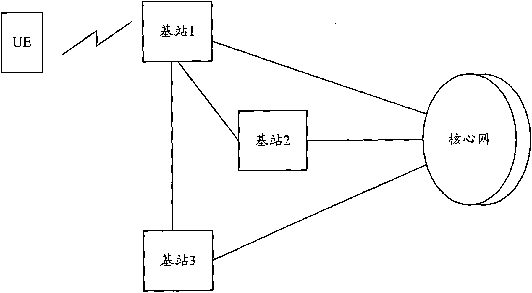
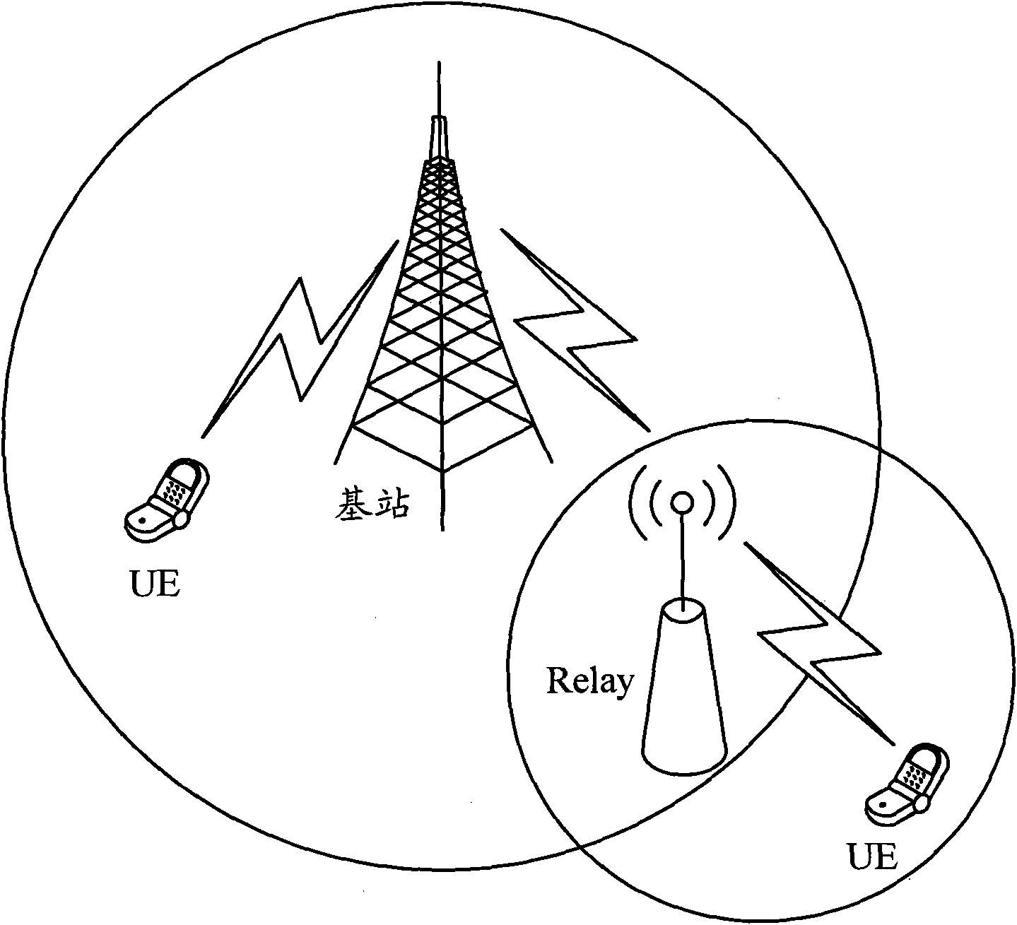
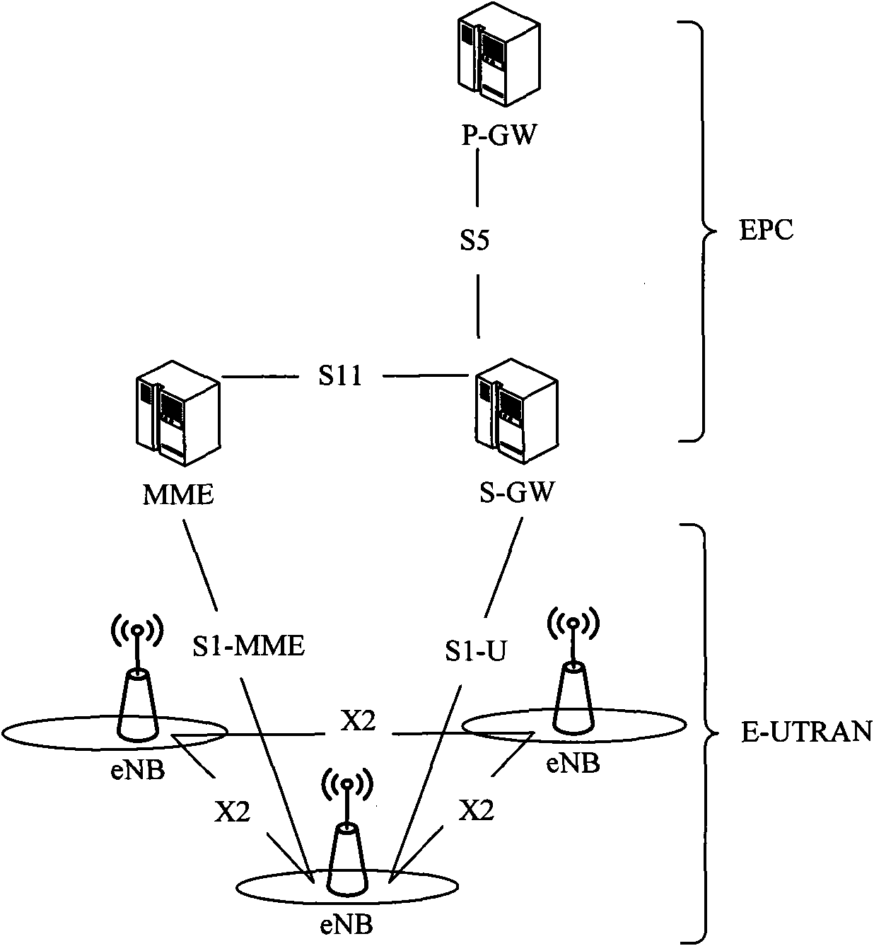
[0067] This example describes a network architecture in the present invention, such as Figure 4 shown. Among them, the Relay has two transmission network access nodes: one is the local LBO GW located on the DeNB, and correspondingly establishes a local transmission channel 101 for the Relay on the DeNB; the other is the Relay P-GW located in the core network, as shown in the figure For simplicity and integration with the S-GW; correspondingly, a remote transmission channel 102 is established for the Relay between the DeNB and the Relay P-GW. Different transmission channels are transmitted by the radio bearer 103 on the Un interface between the Relay and the DeNB.

[0068] The direct interface X2 channel 111 between the Relay and other eNBs, the signaling and data on this interface are used as the service data of the Relay, and are sent from the Relay to the corresponding eNB via the LBO GW on the DeNB through the local transmission channel 101 .

[0069]For UEs accessed by ...

example 2

[0074] This example describes the access process of the relay node in the above example 1. For the architecture, see for example Figure 4 The structure of the example 1, the process of this example is as follows Figure 5 shown, including the following steps:

[0075] Step 501: the Relay is within the wireless coverage of the DeNB, and establishes an RRC connection with the DeNB.

[0076] Step 502: The Relay initiates an Attach request to the core network through non-access stratum signaling, and the request signaling is carried by the RRC message on the air interface and transmitted between the Relay and the DeNB; the DeNB selects an MME for the Relay, and is carried in the S1 message Transfer between the DeNB and the selected MME.

[0077] Step 503: After receiving the Attach request in step 502, the MME selects the P-GW serving the Relay located in the EPC through the registration information of the Relay, or the Relay itself designates a P-GW located in the EPC. And in...

Embodiment 3

[0088] This embodiment describes the access process of the UE under the relay node in the first embodiment above, and the handover process of the UE being handed over from the cell under the jurisdiction of the relay node to the adjacent macro cell. Architecture see eg Figure 4 The structure of the example 1, the process of this example is as follows Figure 6 shown, including the following steps:

[0089] Step 601: The UE is within the wireless coverage of the relay, and establishes an RRC connection with the relay.

[0090] Step 602: The UE initiates an Attach request to the core network through the non-access stratum signaling, and the request signaling is transmitted between the UE and the Relay carried by the RRC message on the air interface, that is, Uu; the Relay selects the MME for the UE and sends it to the S1 message Carrying, the Relay uses the S1 message as service data, enters the remote transmission channel 102 of the Relay through the Un bearer 103 to reach t...


PUM


Abstract

The invention discloses a transmission system applied to a wireless relay. The system comprises at least two transmission network access nodes which are connected with a relay, wherein the relay is simultaneously accessed into a transmission network by a transmission network access node positioned on a core network and a transmission network access node positioned on a Donor NB (DNB) and transmitting relay data on transmission channels which are respectively established among different transmission network access nodes. The invention also discloses a transmission method applied to a wireless relay. The method comprises the following step: the relay is simultaneously accessed into the transmission network by the transmission network access node positioned on the core network and the transmission network access node positioned on the DNB. By adopting the system and the method of the invention, the relay can be simultaneously accessed into the transmission network by two transmission passages, thereby solving the problem of relay data transmission comprising scene switching.

Description

technical field [0001] The invention relates to the field of wireless relay in a cellular wireless communication system, in particular to a transmission system and a transmission method applied to wireless relay technology. Background technique [0002] The cellular wireless communication system is mainly composed of a terminal (UE, User Equipment), a wireless access network and a core network, such as figure 1 as shown, figure 1 Including base station, terminal and core network. Among them, a network composed of base stations, or a network composed of base stations and base station controllers is called a radio access network, and the radio access network is responsible for access layer affairs, such as management of radio resources. There may be physical or logical connections between base stations according to the actual situation, such as figure 1 Base station 1 and base station 2 or base station 3 in . Each base station can be connected to one or more core network n...

Claims


Application Information

Patent Timeline
Patent Type & Authority Applications(China)
IPC IPC(8): H04W24/00
CPCH04W84/047H04B7/155H04W72/04H04W36/0005H04W92/20
Inventor 奚进黄亚达
Owner 深圳市恒程汇文化科技有限公司
Why Eureka
Try Eureka