Roll mark spot wiper for rolling mill

A wiper and rolling mill technology, applied in the field of rolling mills, can solve the problems of poor cleaning effect of manual wiping rolls, affecting the surface precision of rolled parts, unsatisfactory cleaning effect, etc., achieving ideal cleaning effect and low maintenance cost , The effect of eliminating potential safety hazards

Inactive Publication Date: 2011-04-06
BAOSTEEL DEV CO LTD
View PDF0 Cites 7 Cited by
  • Summary
  • Abstract
  • Description
  • Claims
  • Application Information

AI Technical Summary

Problems solved by technology

However, in the process of processing, the fine chips of the steel ingot will inevitably be attached to the roller shaft, and these chips will leave scratches and pits on the surface of the rolled piece during the rolling process, that is, roll marks. , thus affecting the surface accuracy of the rolled piece, and even leading to the scrapping of the rolled piece
[0003] At present, the method of removing stains on the surface of the roller is mainly divided into two steps. The first is manual removal. The crew will use a manual roller wiper (a combination of a wooden stick and a wiping head) to wipe the surface of the roller that produces roller marks. The outer surface is a circumferential surface, the cleaning angle is large, the cleaning effect is often unsatisfactory, and the efficiency is not high. More importantly, since the working roll does not stop during this process, there is a very large problem in the entire manual roll wiping process. Security risks
In addition, due to the poor cleaning effect of manual cleaning, the rolls are often not used for a long time, usually a few hours. When the surface precision of the rolled parts processed by the manually cleaned rolls cannot meet the requirements, the second step is required: Shutdown to replace work rolls, the entire roll change work needs to be shut down for more than 30 minutes, which will affect the output of the entire unit
And because the replaced roller shaft must be processed by the follow-up machine tool before it can continue to be used, the production cost of the product is further increased

Method used


Image

  • Roll mark spot wiper for rolling mill
  • Roll mark spot wiper for rolling mill
  • Roll mark spot wiper for rolling mill

Examples


Embodiment Construction

[0028] The present invention will be further described below in conjunction with accompanying drawing.

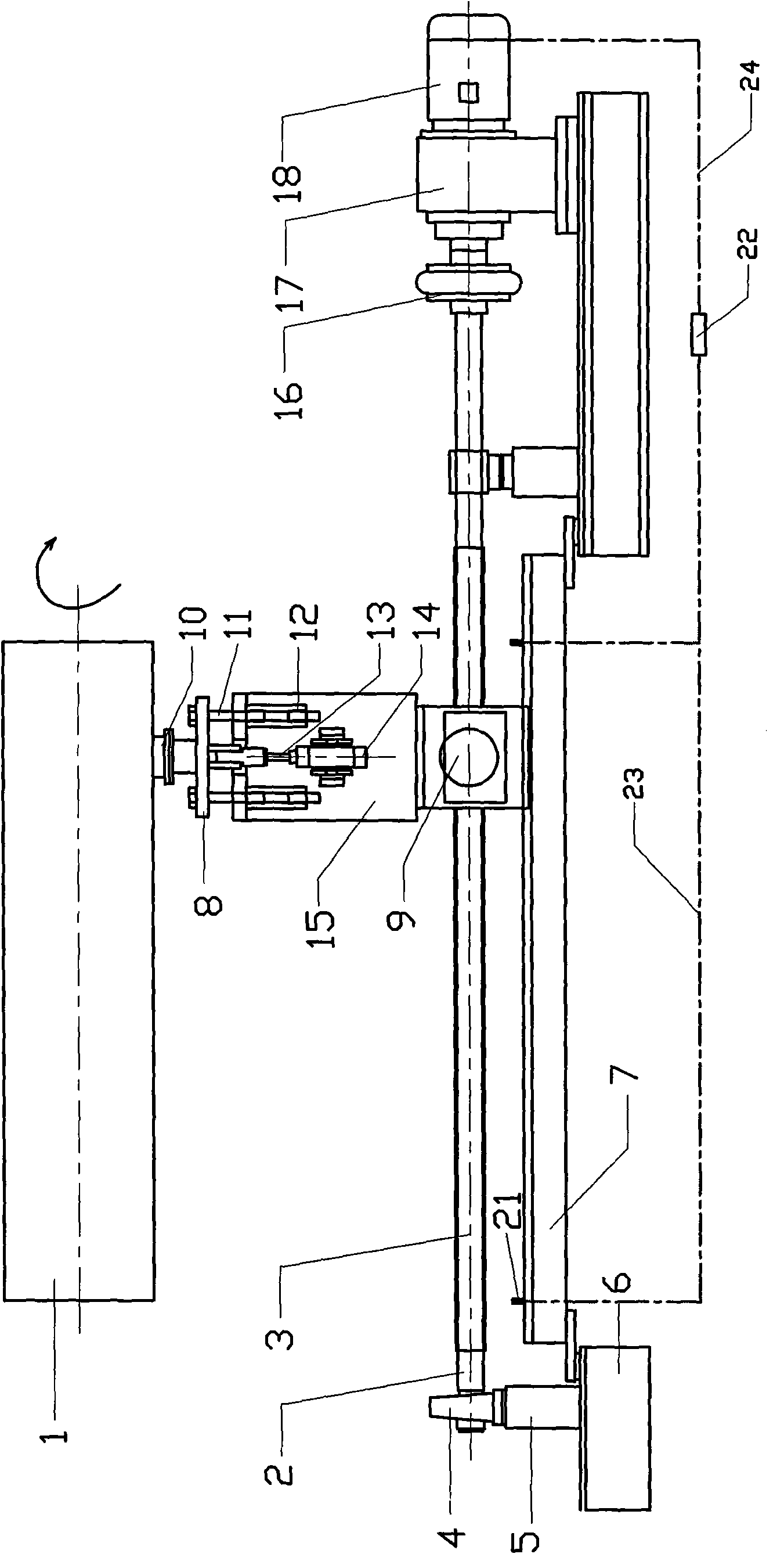
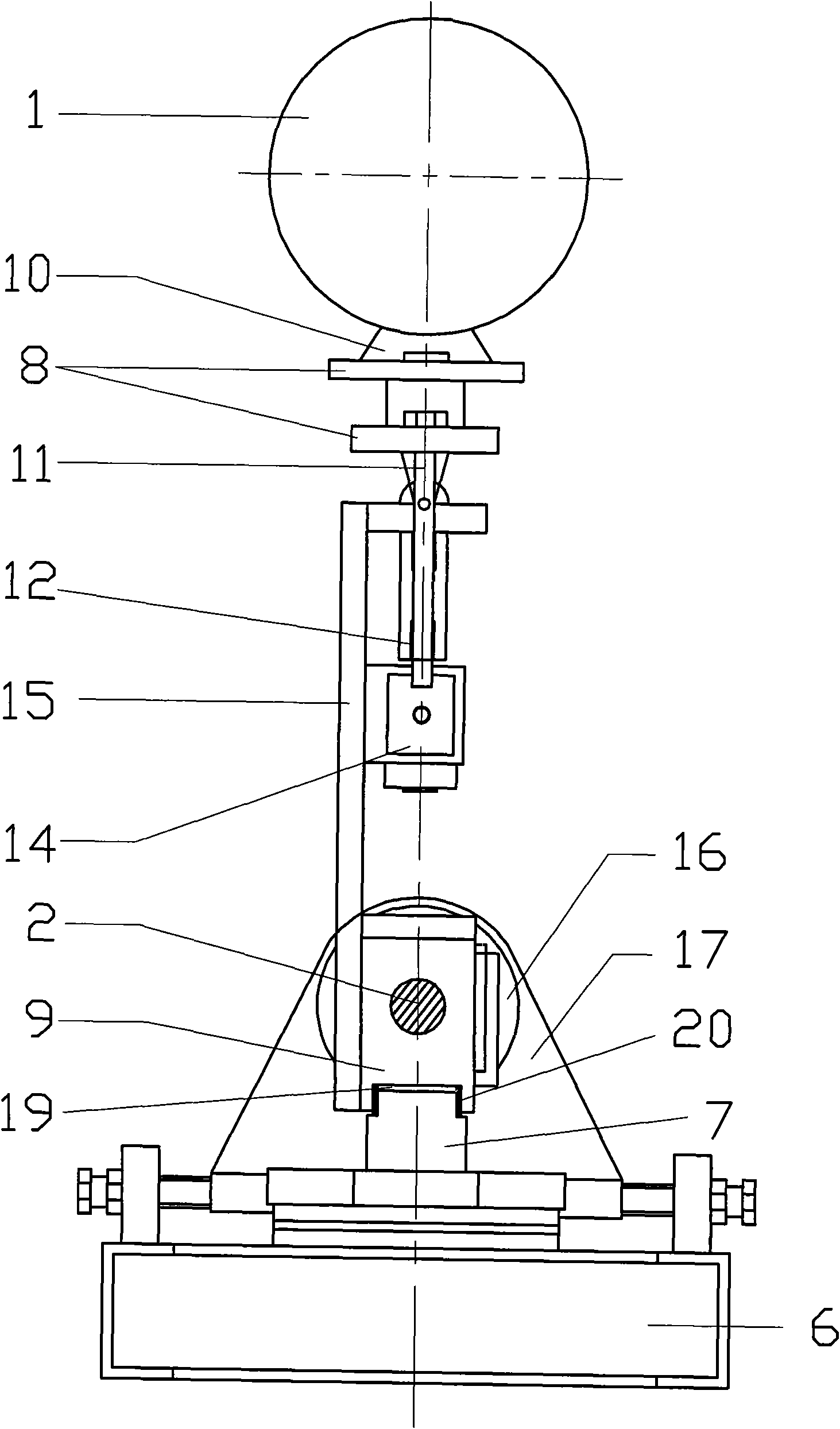
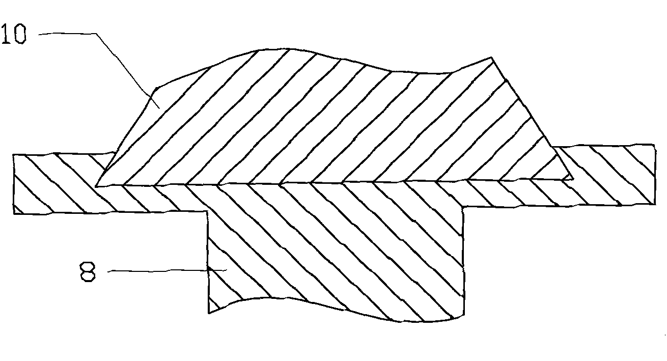
[0029] figure 1 It is a front view of a preferred solution of the present invention. The screw mandrel 2 is installed on the base 6 through the bearing 4 and the bearing seat 5. The threaded section 3 on the screw mandrel is located directly below the working section 1 of the roller shaft. The power transmission and conversion The transmission mode of the screw pair is adopted, the output shaft of the motor 18 is connected with the screw rod 2 through the reduction box 17 and the coupling 16, and a nut 9 matching it is set on the threaded section 3 of the screw rod, and the upper part of the nut 9 is close to the roller shaft. A support 15 is installed on one side of the working section 1, a cylinder 14 is housed on the support 15, and the wiping head 10 is fixed on the movable support 8 on the piston rod 13 upper end of the cylinder 14, and the movable support 8 is fixed w...


PUM


Abstract

The invention relates to a roll mark spot wiper for a rolling mill, comprising a sliding screw pair driven by a motor. The sliding screw pair comprises a screw rod which is arranged in parallel with a roll shaft working segment; the screw rod is provided with a thread segment which is opposite to the roll shaft working segment; the length of a screw rod thread segment is not less than that of theroll shaft working segment; the screw rod thread segment is provided with a nut matched with the screw rod thread segment; one side of the nut, which faces the roll shaft working segment, is fixed with an air cylinder; a piston in the air cylinder is provided with a piston rod extending out of the air cylinder; one extended end of the piston rod is provided with a wiping head; and the wiping headat the working position is in contact with the outer surface of the roll shaft working segment. The manual operation is not needed in the wiping process of the wiper, thereby thoroughly eradicating all potential safety hazards in the manual wiping process and ensuring the manual safety production. Spots on the surface of a roll shaft can be removed in time, the wiping effect is ideal and the product quality is ensured; and the time interval for replacing the roll shaft is prolonged, and the production cost of products is reduced. The roll mark spot wiper has simplicity and convenience in operation and low maintenance cost.

Description

technical field [0001] The present invention relates to rolling mills, and in particular to cleaning of roll shafts of rolling mills. Background technique [0002] In modern iron and steel production, a pair of rollers arranged in parallel and counter-rotating are commonly used to roll steel plates. The rollers apply high pressure to the material under the pressure of the hydraulic system, and the shear force between the two rollers can be used. The ingot is flattened continuously through the pressure zone between the two rolls. However, in the process of processing, the fine chips of the steel ingot will inevitably be attached to the roller shaft, and these chips will leave scratches and pits on the surface of the rolled piece during the rolling process, that is, roll marks. , thus affecting the surface accuracy of the rolled piece, and even leading to the scrapping of the rolled piece. [0003] At present, the method of removing stains on the surface of the roller is mai...

Claims


Application Information

Patent Timeline
Patent Type & Authority Applications(China)
IPC IPC(8): B21B28/04
Inventor 朱小华
Owner BAOSTEEL DEV CO LTD
Why Eureka
Try Eureka