Flange welding method and welding device

A flange welding and flange technology, which is applied in the field of flange welding methods and welding devices, can solve problems such as inability to process qualified products, vibration of steel pipes, and influence on welding quality, so as to achieve ideal welding effects, ensure welding quality, and operate convenient effect

Active Publication Date: 2011-04-06
辽宁锦兴电力金具科技股份有限公司
View PDF5 Cites 36 Cited by
  • Summary
  • Abstract
  • Description
  • Claims
  • Application Information

AI Technical Summary

Problems solved by technology

This welding method is only suitable for seamless round pipes. When it is used for the welding of seamed round pipes, polygonal pipes, tapered pipes and flanges, the steel pipe will vibrate when it rotates.
In addition, because the flange is not fixed, deformation occurs during welding, which affects the welding quality, especially for large-size flanges, and qualified products cannot be processed

Method used


Image

  • Flange welding method and welding device
  • Flange welding method and welding device
  • Flange welding method and welding device

Examples


Embodiment Construction

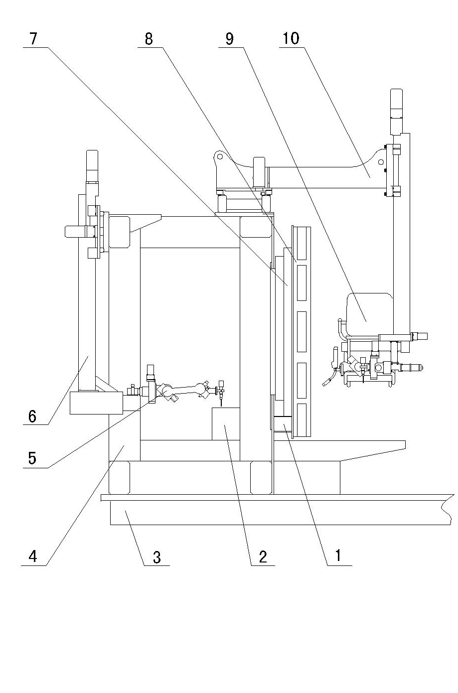
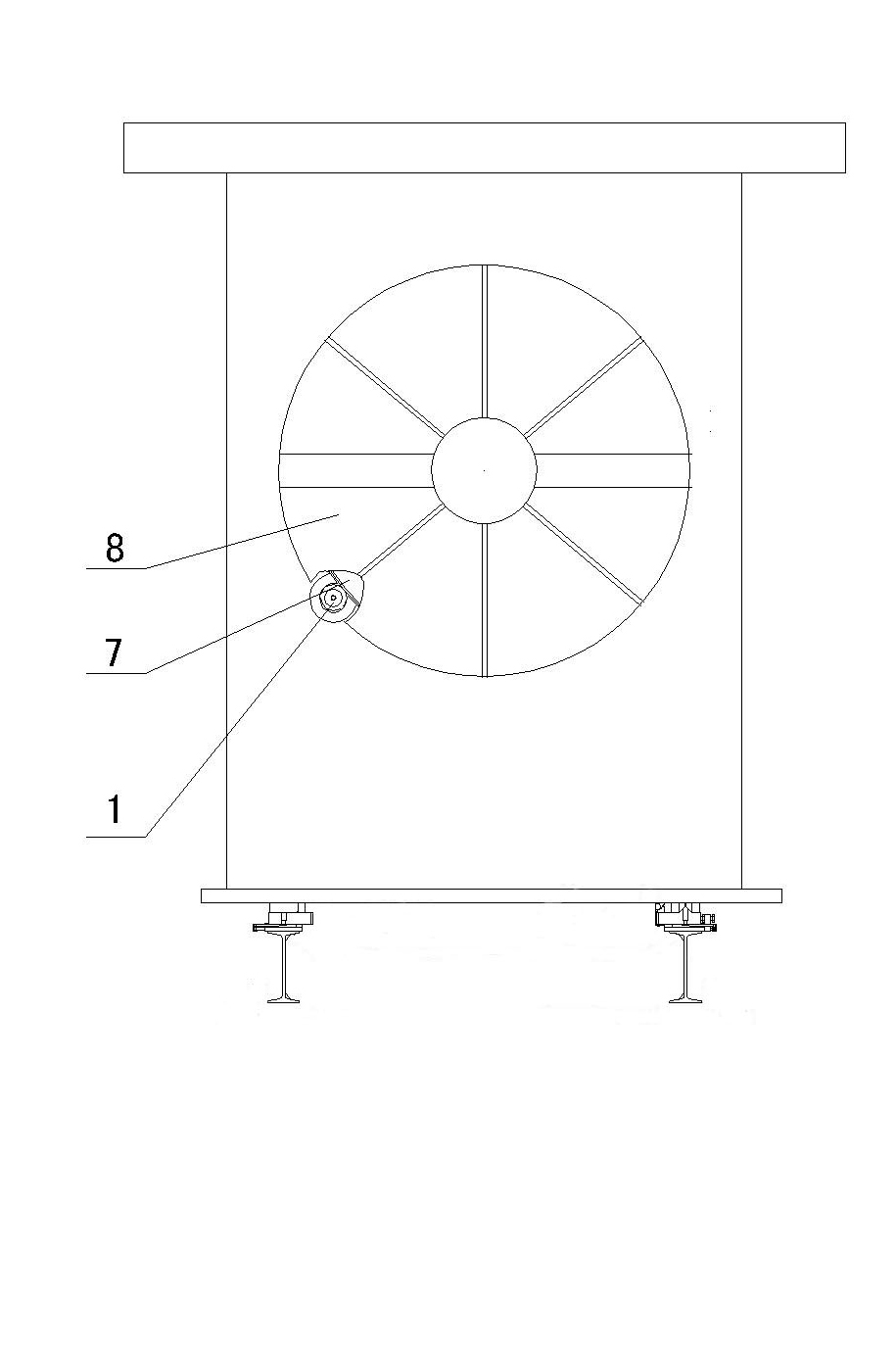
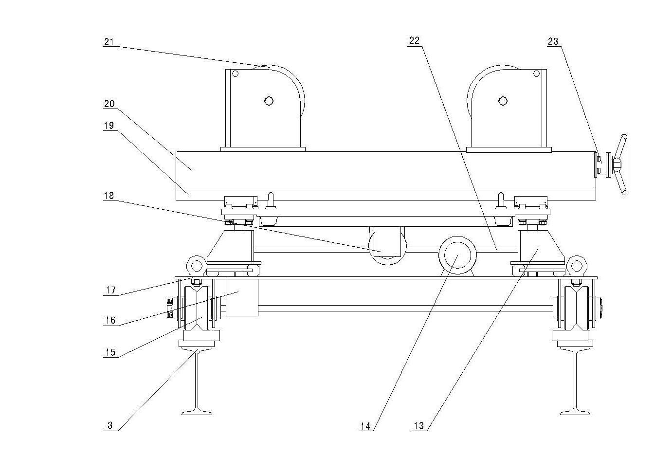
[0021] Such as Figure 1 to Figure 5 Shown, the present invention has two rails 3, is respectively provided with fixed chuck seat 4 and movable chuck seat 12 at the two ends of track 3, is respectively provided with at fixed chuck seat 4 and movable chuck seat 12 horizontal relative positions The chuck 8 is respectively provided with a drive device 2 on the fixed chuck seat 4 and the movable chuck seat 12, the drive device 2 meshes with the rotary support 7 through the gear 1, and the described chuck 8 is fixed on the rotary support 7 On the fixed chuck seat 4 and the inside and outside sides of the movable chuck seat 12, cross brackets 6, 10 are installed respectively, flexible welding equipment 5, 9 are respectively provided on the cross brackets 6, 10, and on the track 3 Two automatic adjustment brackets 11 are arranged, and described automatic adjustment bracket 11 comprises longitudinal translation mechanism 17, and longitudinal translation mechanism 17 can move along tra...


PUM


Abstract

The invention discloses a flange welding method. The method comprises the following steps of: arranging chunk seats at the two ends of rails; arranging flanges on the chunk seats; placing steel tubes on automatic adjusting brackets; adjusting the positions of the steel tubes so as to butt the steel tubes with the flanges; after finishing butting, performing spot-welding on the flanges; removing the automatic adjusting brackets; driving the chunk seats to rotate by using driving devices; and simultaneously driving the flanges to rotate and welding by using welding equipment. A flange welding device comprises two rails; automatic adjusting brackets are arranged on the rails; a fixed chunk seat and a moveable chunk seat are respectively arranged at the two ends of the rails; and rotary supports, the driving devices and flexible welding equipment are arranged on the two chunk seats. The method and the device have the advantages that: the flanges can be prevented from being deforming when welding so as to ensure welding quality; and the steel tubes cannot jitter when welding seam circular tubes, polygonal tubes and conical tubes with the flanges. The horizontal movement of the steel tubes can be realized by using the automatic adjusting brackets so as to realize the accurate butt of the steel tubes and the flanges.

Description

technical field [0001] The invention particularly relates to a flange welding method and a welding device. Background technique [0002] The existing flange welding device is composed of two rails, welding equipment arranged at both ends of the rails, and two automatic adjustment brackets arranged on the rails between the two welding equipments. The automatic adjustment brackets can be moved along the The track moves and can be lifted up and down. Before welding, place the steel pipe on the automatic adjustment bracket, adjust the automatic adjustment bracket so that the steel pipe is in a horizontal position, then fit the flange on both ends of the steel pipe, first spot weld the flange, and the electric motor on the automatic adjustment bracket The roller drives the steel pipe to rotate, and the flange is welded on the steel pipe by welding equipment. This welding method is only suitable for seamless round pipes. When it is used for the welding of seamed round pipes, pol...

Claims


Application Information

Patent Timeline
Patent Type & Authority Applications(China)
IPC IPC(8): B23K31/02B23K37/00B23K37/047
Inventor 王九彪董显林杨永家于艳红
Owner 辽宁锦兴电力金具科技股份有限公司
Why Eureka
Try Eureka